
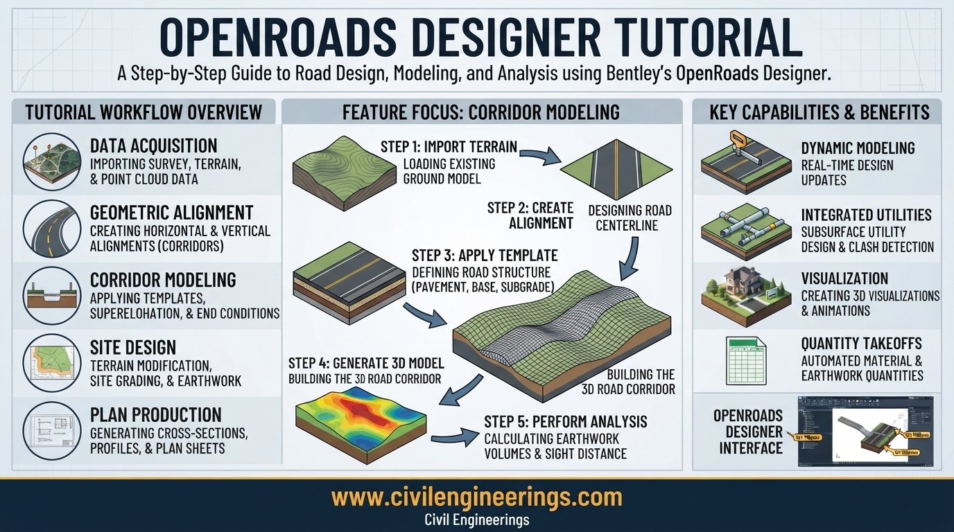
Modern highway projects rarely depend on 2D drafting alone. Engineers now need a coordinated digital model that connects survey information, terrain, horizontal and vertical geometry, roadway templates, corridors, earthworks, drainage, quantities, and construction documentation. That is where OpenRoads Designer becomes particularly useful.
This OpenRoads Designer Tutorial explains the software from a practical highway-engineering perspective rather than treating it as simply another CAD package. The workflow starts with project setup and survey data, then moves through terrain modeling, horizontal alignment, vertical profile design, templates, corridor modeling, superelevation, cross sections, earthwork quantities, and drawing production. Bentley’s current product information describes OpenRoads Designer as a 3D road-design and modeling platform with integrated terrain, corridor, drainage, earthwork, and plan-production capabilities.
Whether you are a civil engineering student learning roadway BIM, a highway engineer developing construction drawings, or a consultant coordinating a multidisciplinary project, understanding the relationship between these components is more important than memorizing individual commands. This guide builds that understanding step by step.
What Is OpenRoads Designer?
OpenRoads Designer is Bentley’s civil infrastructure design application for developing detailed road and highway projects through a model-based workflow. It combines CAD production with civil engineering objects and relationships, allowing design changes to propagate through connected elements.
Instead of drawing a road plan independently from its profile and cross sections, the engineer develops an intelligent model. Horizontal geometry can drive the vertical profile, the profile can control the corridor, and the corridor can generate 3D roadway components and cross sections.
Bentley states that the platform supports 2D and 3D workflows and can automatically generate plans, profiles, and cross sections from the design model.
Why Highway Engineers Use OpenRoads Designer
The major advantage is model continuity.
A conventional drafting workflow may require an engineer to manually update:
- Plan alignment
- Profile drawings
- Typical sections
- Cross sections
- Earthwork quantities
- Construction details
- Roadway annotations
A model-based OpenRoads workflow reduces this duplication because many deliverables originate from the same engineering model.
The software also supports large terrain datasets, point clouds, LiDAR, GIS information, and several common civil-data formats.
Main OpenRoads Designer Components
A typical roadway project involves:
- Project and WorkSet setup
- Survey and reference data
- Existing terrain model
- Horizontal alignment
- Vertical profile
- Template library
- Corridor model
- Superelevation
- Drainage and utilities
- Cross sections
- Earthwork calculations
- Plan and profile sheets
- Construction documentation
The order can vary by project, but maintaining logical dependencies is critical.
Getting Started With OpenRoads Designer
Before creating geometry, establish the project environment correctly.
Bentley’s onboarding material specifically includes selecting the appropriate WorkSpace and WorkSet, creating a DGN file, attaching references, activating terrain, and configuring 2D and 3D model views.
Set Up the WorkSpace and WorkSet
The WorkSpace controls the broader project environment, standards, configuration, and resources. The WorkSet provides the project-specific working environment.
Do not treat these settings as administrative details.
A poorly configured project can create problems with:
- Design standards
- Units
- Seed files
- Feature definitions
- Annotation
- Templates
- Survey styles
- Civil cells
- File organization
For a professional project, establish naming conventions before production begins.
Create the Design File
Create the appropriate DGN model using the project’s approved seed and coordinate system.
Confirm:
- Working units
- Geographic coordinate system
- Project datum
- Survey coordinates
- Design file location
- Reference file structure
- Annotation standards
Coordinate-system errors can produce serious positional discrepancies even when the road geometry itself appears correct.
Understand the Interface
The OpenRoads interface organizes tools through ribbon-based workflows. Bentley’s current training material covers interface navigation, civil-element selection, properties, model exploration, multiple views, and civil-data analysis.
For beginners, learn these areas first:
- Home
- Geometry
- Terrain
- Corridors
- Modeling
- Drawing Production
- Explorer
- Properties
Do not try to memorize every command. Learn what engineering problem each tool solves.
Importing Survey Data and Creating Existing Terrain
Existing ground is the foundation of roadway modeling. If the terrain model is inaccurate, subsequent alignment, grading, earthwork, and drainage decisions can also become unreliable.
Bentley’s learning material describes terrain creation from formats including DTM, XML, TIN, TXT, LandXML, point data, LiDAR, and other sources.
Import Survey Information
Depending on the survey workflow, source information may include:
- Total-station XYZ data
- GPS survey points
- Breaklines
- Contours
- LiDAR
- Drone-derived point clouds
- Existing DTM
- LandXML terrain
- GIS elevation information
Before importing, verify the coordinate system and units.
Build the Existing Terrain Model
A simplified workflow is:
- Open the terrain tools.
- Select the appropriate import method.
- Define the source data format.
- Map point or feature information.
- Apply appropriate feature definitions.
- Create the terrain model.
- Review the terrain boundary.
- Display contours and spot elevations.
- Inspect suspicious triangles.
- Compare the model with survey control.
The last steps are essential.
A terrain model should never be accepted simply because the import command completed successfully.
Terrain Quality-Control Checks
Look for:
- Long or abnormal triangulation
- Incorrect breaklines
- Missing survey points
- Duplicate points
- Vertical spikes
- Incorrect boundaries
- Water bodies modeled incorrectly
- Bridges represented as ground surfaces
- Vegetation or buildings incorrectly influencing the surface
For road design, breaklines are particularly important around drainage channels, curbs, pavement edges, ridges, and other abrupt changes.
Creating Horizontal Road Alignment
Once the existing terrain is ready, the next major task is horizontal geometry.
Horizontal alignment establishes the road’s plan position through tangents, circular curves, spirals, transitions, and related geometry.
Start With Design Criteria
Before drawing an alignment, establish the controlling design requirements.
Typical inputs include:
- Design speed
- Road classification
- Lane width
- Shoulder width
- Minimum horizontal radius
- Maximum superelevation
- Sight-distance requirements
- Intersection requirements
- Right-of-way constraints
- Terrain limitations
The software can calculate geometry, but the engineer must decide which design criteria apply.
Create the Horizontal Alignment
OpenRoads provides horizontal geometry tools for lines, arcs, reverse curves, spirals, offsets, tapers, and complex geometry.
A basic workflow is:
- Select the appropriate geometry workflow.
- Define the horizontal design standard.
- Create the initial tangent.
- Add horizontal curves.
- Add transition elements where required.
- Assign alignment names and descriptions.
- Review stationing.
- Check radii and tangent lengths.
- Evaluate sight distance and design constraints.
Horizontal Curve Fundamentals
For a simple circular curve, the approximate tangent length is:
T = R tan(Δ/2)
Where:
- T = tangent length
- R = curve radius
- Δ = intersection or central angle
The curve length is:
L = πRΔ/180
where Δ is expressed in degrees.
These equations remain useful even when software performs the calculations automatically. An engineer should understand the geometry behind the command.
Practical Alignment Review
Do not judge an alignment only by whether the software reports it as valid.
Review:
- Sudden radius changes
- Short tangents
- Reverse curves
- Compound curves
- Transition lengths
- Intersection visibility
- Terrain impacts
- Property constraints
- Drainage implications
A mathematically valid alignment can still be poor engineering.
Creating the Vertical Profile
The vertical profile determines the road’s elevation along the horizontal alignment.
It controls:
- Grades
- Crest curves
- Sag curves
- Drainage behavior
- Earthwork
- Vertical clearance
- Driver comfort
- Sight distance
Create an Existing-Ground Profile
After establishing the horizontal alignment and active terrain:
- Open the profile model.
- Select the terrain surface.
- Select the alignment.
- Generate the existing-ground profile.
- Review elevation against station.
The resulting profile provides the base for proposed vertical design.
Develop the Proposed Profile
Create the proposed vertical geometry using:
- Tangent grades
- Vertical curves
- PVI locations
- Design elevations
- Minimum and maximum grades
A simplified parabolic vertical curve relationship can be expressed through the rate of change of grade:
K = L/A
Where:
- K = curve parameter
- L = vertical curve length
- A = algebraic difference between grades
For example, if two grades are +2% and −1%, then:
A = |−1 − (+2)| = 3%
The required curve length depends on the applicable design criteria and sight-distance requirements.
Profile Quality Checks
Check the proposed profile for:
- Excessive grades
- Short vertical curves
- Poor drainage
- Low points
- High points
- Earthwork balance
- Bridge clearance
- Culvert crossings
- Intersection elevations
This is where civil-engineering judgment becomes more important than software operation.
Creating Roadway Templates
Templates are one of the most important concepts in OpenRoads Designer.
A template defines the cross-sectional behavior of the roadway. It can include pavement, shoulders, curbs, sidewalks, medians, side slopes, ditches, barriers, and other components.
Bentley’s learning material describes templates as collections of constrained roadway components and explains their use in corridor modeling and end conditions.
What Is a Roadway Template?
Think of a template as a parametric cross section.
For a two-lane road, it may contain:
- Lane components
- Shoulder components
- Pavement layers
- Crown
- Side slopes
- Ditches
- Daylight lines
The template can then be applied along an alignment.
Template Constraints
Template points commonly use horizontal, vertical, and slope constraints.
For example:
- Lane width = 3.5 m
- Shoulder width = 2.0 m
- Crossfall = 2%
- Side slope = 1V:2H
These values should come from project design criteria rather than arbitrary software defaults.
End Conditions
End conditions connect the proposed roadway to the existing terrain.
They may represent:
- Cut slopes
- Fill slopes
- Ditches
- Benches
- Retaining conditions
- Special grading
Incorrect end conditions can produce unrealistic earthworks even when the pavement geometry looks correct.
Building the Corridor Model
The corridor brings alignment, profile, templates, terrain, and design controls together.
Bentley’s learning guide describes a corridor as a collection of templates scheduled along an alignment, with transitions and related controls.
Create a New Corridor
A typical process is:
- Select the proposed horizontal alignment.
- Select the proposed vertical profile.
- Create a new corridor.
- Define the corridor limits.
- Assign a template.
- Set template drop stations.
- Add transitions.
- Define targets where necessary.
- Process the corridor.
- Review the 3D model.
Template Drops
A template drop controls where a particular template applies.
For example, a road might use:
- Standard section from 0+000 to 2+000
- Turn-lane section from 2+000 to 2+300
- Intersection template from 2+300 to 2+450
- Standard section after 2+450
This allows the model to represent changing roadway conditions.
Corridor References and Targeting
Complex projects may require one corridor to respond to another corridor, terrain surface, alignment, or design feature.
Targeting is particularly useful for:
- Intersections
- Tie-ins
- Medians
- Turn lanes
- Parallel roads
- Abutments
- Complex grading
Bentley’s onboarding exercises specifically cover target aliasing, corridor references, end-condition exceptions, and corridor clipping.
Superelevation Design
Superelevation provides cross slope on horizontal curves to help accommodate vehicle dynamics.
The basic relationship commonly used in highway engineering is:
e + f = V²/(127R)
for metric units when:
- e = superelevation rate
- f = side-friction factor
- V = speed in km/h
- R = radius in metres
The actual values and distribution method must follow the governing design standard.
OpenRoads provides dedicated superelevation tools for creating, calculating, editing, and applying superelevation within corridor workflows.
Superelevation Workflow
A practical sequence is:
- Identify eligible horizontal curves.
- Confirm design speed.
- Select the applicable standard.
- Calculate superelevation.
- Review runoff and runout.
- Inspect lane cross slopes.
- Check transition stations.
- Apply the resulting controls to the corridor.
- Review dynamic sections.
Never assume that software-generated superelevation is automatically acceptable. Check the result against the project standard.
Creating Cross Sections and Reviewing the 3D Model
Cross sections provide one of the best ways to verify whether the roadway model behaves correctly.
Bentley’s current training pathway includes corridor modeling, 3D review, dynamic cross sections, and drawing production as connected stages of the workflow.
Dynamic Cross Sections
Use cross sections to inspect:
- Pavement width
- Shoulder width
- Side slopes
- Ditches
- Cut and fill
- Existing ground
- Proposed ground
- Superelevation
- Transitions
- Utility conflicts
Move through the alignment station by station rather than checking only a few representative sections.
3D Model Review
A 3D view can expose problems that are difficult to see in plan view.
Inspect:
- Road surface continuity
- Intersection grading
- Drainage paths
- Embankment tie-ins
- Cut slopes
- Bridge approaches
- Median transitions
- Ramp connections
Civil Cells can also help create repeatable junctions and roadway layouts while keeping geometry and corridor relationships coordinated. Bentley describes their use for repeatable junction, taper, slip-road, and tie-in arrangements.
Earthwork and Quantity Analysis
Once the corridor model is established, engineers can evaluate excavation and embankment requirements.
OpenRoads Designer supports earthwork calculations using triangulated and end-area approaches and provides customizable earthwork reporting.
Cut and Fill Concepts
For a simple average-end-area calculation:
V = (A₁ + A₂)L/2
Where:
- V = volume
- A₁ = first cross-sectional area
- A₂ = second cross-sectional area
- L = distance between sections
In actual digital terrain workflows, quantities can be derived from surface comparisons and detailed 3D models.
Quantity Quality Control
Check whether quantities account for:
- Existing ground
- Proposed ground
- Topsoil stripping
- Pavement excavation
- Rock excavation
- Unsuitable material
- Shrinkage or swell
- Benching
- Haul requirements
Do not use software quantities blindly for tendering. Confirm the project’s quantity methodology and measurement rules.
Drainage and Utility Design
Road geometry cannot be separated from drainage.
A profile that looks acceptable from a geometric perspective may create poor drainage if low points, crossfall, ditch grades, or outfalls are ignored.
OpenRoads Designer includes drainage and utility capabilities covering storm and sanitary systems, hydraulic analysis, culverts, ponds, and related infrastructure.
Basic Road Drainage Checks
Review:
- Longitudinal grade
- Crossfall
- Sag points
- Catchment areas
- Inlets
- Culverts
- Side drains
- Outfalls
- Hydraulic capacity
- Flood levels
For hydraulic calculations, use the methodology required by the project authority. For example, a rational-method relationship may be written as:
Q = CIA
where:
- Q = peak runoff
- C = runoff coefficient
- I = rainfall intensity
- A = drainage area
The units and coefficient conventions must match the adopted standard.
Drawing Production and Documentation
The final model must become useful construction information.
OpenRoads supports plan and profile production, cross-section sheets, annotation, tables, reporting, and common export formats.
Plan and Profile Sheets
A typical drawing package may include:
- Key plan
- Alignment plan
- Profile
- Typical sections
- Cross sections
- Drainage plans
- Utility plans
- Pavement details
- Intersection details
- Quantity schedules
Named boundaries and drawing-production tools help automate the process of creating sheets from the model.
Annotation
Before issuing drawings, verify:
- Stationing
- Elevations
- Alignment names
- Profile grades
- Curve information
- North arrows
- Scales
- Sheet references
- Design notes
- Construction limits
Automated annotation saves time, but every issued sheet still requires engineering review.
Common OpenRoads Designer Mistakes
Beginners often focus on learning commands while overlooking model management.
Mistake 1: Starting Geometry Before Validating Survey Data
If the existing ground is wrong, alignment and earthwork decisions can become unreliable.
Better approach: validate survey control and terrain before detailed design.
Mistake 2: Ignoring Feature Definitions
Civil elements need meaningful definitions so the model remains organized and reportable.
Better approach: establish project standards before production.
Mistake 3: Building Too Many Manual Elements
Manual drafting can break the relationship between model components.
Better approach: use intelligent geometry, templates, corridors, and civil elements wherever practical.
Mistake 4: Treating Templates as Simple Graphics
A template is not merely a drawing of a typical section. It controls modeled behavior.
Better approach: understand constraints, components, point controls, end conditions, and parametric behavior.
Mistake 5: Trusting Automated Design Without Engineering Review
Software can calculate a curve, profile, or corridor. It cannot replace engineering responsibility.
Better approach: independently verify design criteria and project requirements.
Best Practices for Students, Engineers, and Contractors
Recommendations for Civil Engineering Students
Students should learn highway-engineering fundamentals before trying to master every OpenRoads command.
Focus on:
- Horizontal alignment
- Vertical alignment
- Superelevation
- Earthwork
- Roadway cross sections
- Drainage
- Survey data
- Highway design standards
Then reproduce a small road project from survey to final sheets.
Recommendations for Highway Engineers
Engineers should build a controlled model rather than simply producing attractive 3D graphics.
Maintain:
- Design criteria
- Model naming standards
- Revision control
- Terrain quality checks
- Geometry checks
- Corridor validation
- Quantity checks
- Drawing reviews
Bentley’s learning resources currently provide dedicated courses for geometry, terrain, corridor modeling, plan/profile sheets, and cross-section production.
Recommendations for Contractors
Contractors can benefit from understanding the model even when they are not responsible for design.
Use the model to investigate:
- Existing versus proposed levels
- Construction limits
- Earthwork
- Pavement geometry
- Drainage
- Tie-ins
- Quantities
However, construction teams should always work from the contractually approved drawings, specifications, models, and revisions applicable to the project.
IRC, AASHTO, and ICE Considerations
OpenRoads Designer is a design platform, not a substitute for a governing highway design standard.
For projects in India, engineers should consult the latest applicable Indian Roads Congress publications. IRC’s current publication information includes IRC:73-2023, Geometric Design Standards for Non-Urban Roads, among other road-design documents.
IRC maintains technical committees covering transport planning, flexible and rigid pavements, drainage, rural roads, road safety, urban roads, composite pavement, and other highway disciplines.
For projects using AASHTO criteria, the engineer should use the current project-approved AASHTO publications and agency supplements rather than relying on generic software defaults.
For UK-oriented work, ICE guidance emphasizes the relationship between accurate site information, engineering principles, design software, geometric design, drainage, and project quality management.
The key principle is simple: configure OpenRoads to implement the applicable engineering standard; do not allow the software to define the engineering standard.
OpenRoads Designer Tutorial: A Practical Learning Sequence
A beginner can follow this progression:
Stage 1 — Interface
Learn views, models, Explorer, properties, references, and civil-element selection.
Stage 2 — Terrain
Import survey information and create, inspect, and edit an existing terrain model.
Stage 3 — Geometry
Create horizontal alignments and vertical profiles.
Stage 4 — Templates
Build or modify a roadway template with appropriate constraints and end conditions.
Stage 5 — Corridor
Create a corridor, assign templates, establish template drops, and review the 3D model.
Stage 6 — Superelevation
Calculate, review, and apply crossfall transitions.
Stage 7 — Cross Sections
Inspect dynamic sections and verify pavement, slopes, terrain, and earthworks.
Stage 8 — Drainage
Develop drainage and utility components while checking road grading and hydraulic requirements.
Stage 9 — Quantities
Review earthwork and other model-derived quantities.
Stage 10 — Documentation
Generate plan/profile sheets, cross-section sheets, annotations, schedules, and final deliverables.
This progression closely reflects Bentley’s own learning structure, which includes geometry, terrain display, corridor modeling, plan/profile production, and cross-section production.
Frequently Asked Questions
1. What is OpenRoads Designer used for?
OpenRoads Designer is used for detailed civil and highway design, including terrain modeling, road geometry, corridor modeling, superelevation, drainage, earthworks, quantities, and construction documentation.
2. Is OpenRoads Designer difficult for beginners?
The software can appear complex because it combines CAD, BIM, terrain, geometry, and corridor modeling. Beginners generally progress faster when they learn highway-engineering concepts first and then connect each concept to the corresponding tool.
3. Can OpenRoads Designer create horizontal and vertical alignments?
Yes. Its geometry tools support horizontal elements such as lines, arcs, spirals, offsets, and complex geometry, along with vertical geometry tools for profiles and curves.
4. What is a template in OpenRoads Designer?
A template is a parametric roadway cross section made from constrained components and points. It defines how pavement, shoulders, slopes, ditches, and other elements behave within a corridor.
5. What is a corridor in OpenRoads Designer?
A corridor is a modeled roadway system created by applying templates along an alignment and profile, with controls and transitions used to represent changing conditions.
6. Can OpenRoads Designer calculate earthwork quantities?
Yes. Bentley identifies earthwork modeling and reporting, including triangulated and end-area volume workflows, as part of the platform’s capabilities.
7. Can OpenRoads Designer work with survey and LiDAR data?
Yes. Bentley states that the platform can import terrain information from numerous formats and sources, including point clouds, LiDAR, ASCII data, LandXML, and other civil formats.
8. Does OpenRoads Designer replace highway design standards?
No. It implements design workflows, but engineers must select and apply the standards required by the relevant client, authority, and jurisdiction.
9. Is OpenRoads Designer useful for BIM road projects?
Yes. Its model-based approach connects roadway geometry, terrain, corridor components, documentation, and other infrastructure information. Bentley also provides workflows for iModels and infrastructure collaboration.
10. What should I learn first in OpenRoads Designer?
Start with interface navigation, project setup, terrain, horizontal geometry, vertical profiles, templates, and corridor modeling. After that, progress to superelevation, cross sections, drainage, quantities, and drawing production.
Conclusion
Learning OpenRoads Designer is much easier when the software is treated as a complete highway-engineering workflow rather than a collection of CAD commands. The strongest users understand why a terrain model matters, how horizontal and vertical geometry interact, why templates require careful constraints, and how a corridor transforms design information into a coordinated 3D roadway model.
This Open Roads Designer Tutorial provides a practical foundation covering project setup, survey and terrain modeling, horizontal alignment, vertical profiles, templates, corridor modeling, superelevation, cross sections, drainage, earthwork, and drawing production. Bentley’s current learning resources reinforce this progression through dedicated training in geometry, terrain, corridor modeling, and drawing production.
For students, the best approach is to build a small complete project. For practicing engineers, quality control and design-standard compliance should remain central. Contractors can gain significant value by understanding the model and its relationship to construction documentation. Ultimately, OpenRoads Designer becomes most powerful when engineering judgment, reliable survey information, appropriate standards, and disciplined model management work together.
