
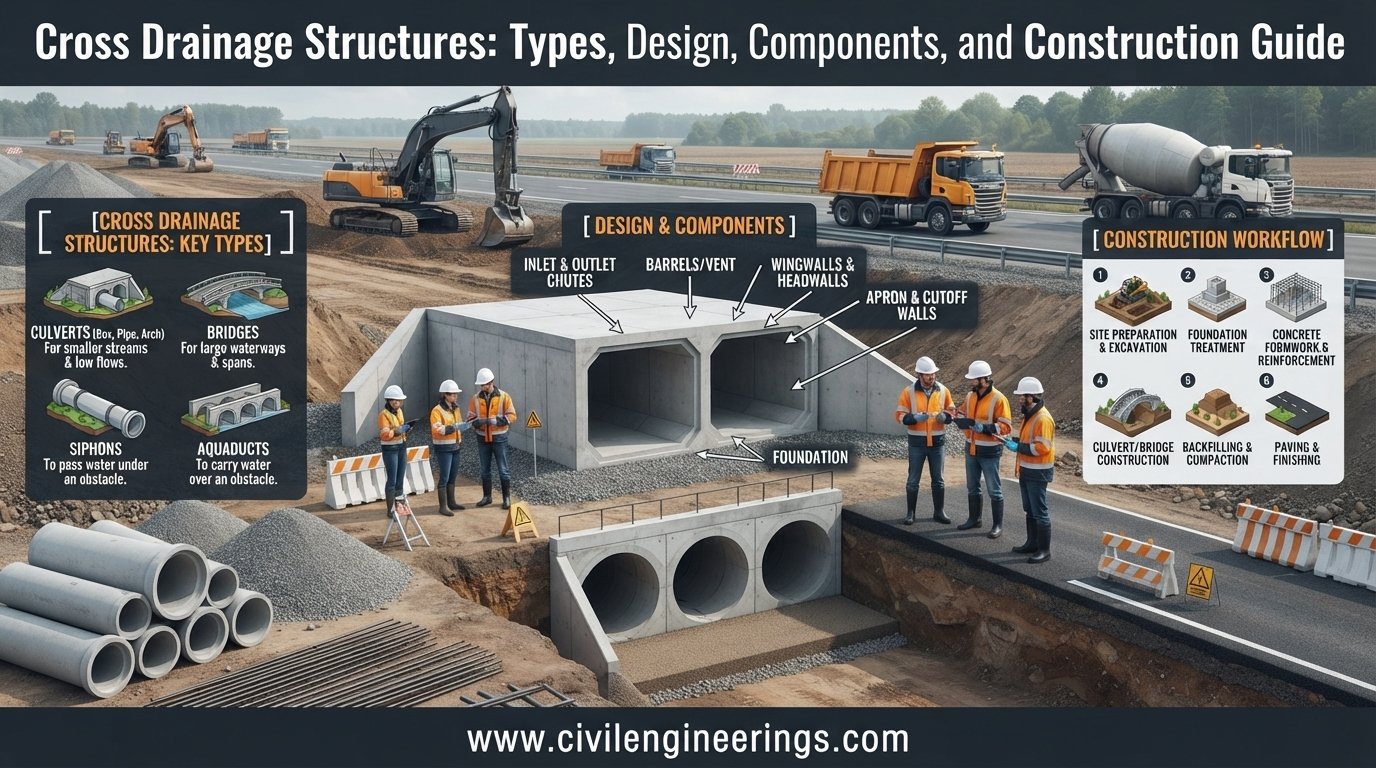
Cross drainage structures are essential elements of highway and road infrastructure wherever a roadway intersects a natural drainage path, stream, canal, or other watercourse. Without an appropriate drainage crossing, runoff can accumulate against the embankment, weaken pavement layers, erode slopes, and eventually damage the road.
Cross Drainage Structures provide a controlled passage for water beneath or through a road embankment while maintaining the required roadway geometry and hydraulic performance. Their selection depends on catchment characteristics, discharge, channel conditions, road formation level, soil properties, flood levels, and construction constraints.
For highway engineers, consultants, contractors, and students, understanding these structures goes beyond memorizing their types. Proper design requires coordination between hydrology, hydraulics, geotechnical engineering, structural engineering, and highway design. This guide explains the major types, components, design principles, hydraulic considerations, construction practices, common failures, and practical recommendations for delivering reliable drainage crossings.
What Are Cross Drainage Structures?
A cross drainage structure is a hydraulic structure constructed where a road or highway crosses an existing drainage channel or watercourse. It allows stormwater or streamflow to pass safely across the roadway without interrupting traffic or compromising the road embankment.
In simple terms, imagine a road constructed across a natural stream. The road embankment blocks the original flow path. Engineers therefore provide a hydraulic opening through the embankment. That opening may consist of a pipe, box, slab culvert, bridge, or another suitable structure.
The primary purpose is to:
- Convey design discharge safely.
- Prevent flooding of the roadway.
- Protect the road embankment from erosion.
- Maintain natural or required drainage patterns.
- Reduce waterlogging around the pavement.
- Protect pavement and subgrade strength.
- Improve road safety during heavy rainfall.
- Control erosion at inlet and outlet locations.
The structure must provide sufficient hydraulic capacity while also carrying traffic loads and resisting earth pressure, water pressure, scour, uplift, and other relevant forces.
Why Cross Drainage Structures Are Important in Highway Engineering
Roads divide natural drainage networks. Every embankment can potentially obstruct surface runoff. If engineers ignore this interaction, even a well-designed pavement can experience premature deterioration.
A properly designed drainage crossing performs several functions simultaneously.
Protecting the Road Embankment
Water flowing against an embankment can cause erosion, slope instability, piping, and saturation. A properly sized crossing transfers water through the roadway rather than allowing uncontrolled overtopping.
Maintaining Pavement Performance
Excess moisture is one of the major enemies of pavement systems. Water entering the base, subbase, or subgrade can reduce bearing capacity and accelerate rutting, cracking, settlement, and deformation.
Preventing Roadway Flooding
A hydraulic opening must accommodate the selected design flood without creating unacceptable upstream flooding or roadway overtopping.
Controlling Scour
Fast-moving water can erode soil around the inlet, outlet, foundations, and channel bed. Headwalls, wing walls, aprons, riprap, gabions, cutoff walls, and energy-dissipation measures may therefore become necessary.
Supporting Transportation Reliability
A drainage structure that fails during a major storm can close a highway, damage vehicles, interrupt emergency access, and generate substantial repair costs. Good drainage design therefore contributes directly to infrastructure resilience.
Major Types of Cross Drainage Structures
Engineers select the structure according to hydraulic demand, crossing geometry, soil conditions, span requirements, available construction materials, and project economics.


Pipe Culverts
Pipe culverts are among the most common solutions for relatively small drainage crossings.
They may use:
- Reinforced concrete pipes
- Corrugated metal pipes
- High-density polyethylene or other approved materials
- Other project-approved pipe systems
Circular pipes are economical and comparatively straightforward to install. Engineers consider pipe diameter, slope, inlet configuration, roughness, headwater depth, tailwater, and outlet protection during hydraulic design.
Multiple pipes may be installed where one opening cannot provide sufficient capacity.
Box Culverts
A box culvert generally consists of a reinforced concrete rectangular or square opening.
Box culverts work particularly well when:
- The required waterway opening is relatively wide.
- Vertical clearance is limited.
- Structural loading is substantial.
- A flat-bottomed flow passage is desirable.
- The project requires a relatively shallow structure.
Single-cell and multi-cell configurations are common.
Slab Culverts
A slab culvert typically consists of a reinforced concrete slab supported by masonry, concrete, or reinforced concrete walls.
It may be suitable for relatively small streams and shallow crossings where site conditions permit economical construction.
The structural system must adequately resist dead load, traffic surcharge, earth pressure, hydraulic effects, and other applicable loads.
Arch Culverts
Arch-shaped structures can provide a useful hydraulic opening while reducing certain structural requirements depending on geometry and construction method.
They may be constructed using masonry, concrete, or prefabricated systems. Their application depends heavily on local materials, structural requirements, and hydraulic conditions.
Causeways
A causeway allows water to pass over or through the roadway under controlled conditions. Engineers may use them where flooding is frequent and construction of a conventional high-level bridge or culvert would not be economically justified.
However, overtopping must be treated as a deliberate design condition rather than an accidental event. Warning systems, pavement protection, hydraulic stability, and traffic safety become particularly important.
Bridges
Where the watercourse is large, deep, unstable, or environmentally sensitive, a bridge may provide the most appropriate crossing.
Bridges generally provide a larger waterway opening than culverts and can reduce obstruction of the natural channel. They also involve more extensive structural, geotechnical, hydraulic, and foundation design.
Classification Based on Road and Watercourse Relationship
Cross drainage arrangements can also be considered according to the relationship between the road and the drainage channel.
Road Crossing a Natural Watercourse
This is the most familiar situation. The road crosses a stream or natural drainage channel, and a culvert or bridge carries the water beneath the road.
Road Crossing an Irrigation or Artificial Channel
A highway may intersect an irrigation canal, drainage ditch, or other engineered watercourse. The crossing must account for the existing channel dimensions, operating conditions, water levels, maintenance requirements, and ownership constraints.
Drainage Crossing at a Skew Angle
Not every watercourse crosses a highway at 90 degrees.
A skew crossing occurs when the channel meets the roadway at an angle. Engineers must evaluate the hydraulic and structural consequences because an unsuitable alignment can increase flow resistance, construction complexity, and maintenance requirements.
Main Components of a Cross Drainage Structure
Although components vary according to structure type, a typical culvert crossing may contain several important elements.
Inlet
The inlet receives water and guides it into the drainage opening.
An inlet may incorporate:
- Headwall
- Wing walls
- Apron
- Inlet channel
- Trash protection where appropriate
- Erosion protection
The inlet geometry can significantly influence hydraulic efficiency.
Culvert Barrel
The barrel is the principal water-conveyance passage beneath the road.
Its important characteristics include:
- Shape
- Diameter or dimensions
- Length
- Slope
- Material
- Surface roughness
- Structural capacity
- Joint configuration
Outlet
The outlet releases water downstream. Engineers must prevent excessive velocity and local erosion.
Outlet protection may include concrete aprons, riprap, gabions, stilling arrangements, cutoff walls, or other approved energy-control measures.
Headwalls and Wing Walls
Headwalls retain the embankment and help guide flow into or out of the structure.
Wing walls extend outward from the headwall and help transition between the roadway embankment and the watercourse.
Aprons and Cutoff Walls
An apron can protect the channel bed near the inlet or outlet. Cutoff walls may reduce the risk of undermining and piping beneath the structure.
Hydrological Design of Cross Drainage Structures
Hydrology determines how much water the structure needs to convey. The hydraulic design then determines how that discharge can safely pass through the opening.
The first major question is:
What design discharge should the structure accommodate?
The answer depends on the drainage area, rainfall characteristics, catchment response, flood frequency, land use, soil characteristics, and applicable design standards.
Rational Method
For relatively small catchments, the Rational Method may be appropriate where permitted by the applicable design standard:
where:
- = peak runoff, m³/s
- = runoff coefficient
- = rainfall intensity, mm/hour
- = drainage area, km²
The method has limitations and should not automatically be applied to every catchment.
For larger or more complex watersheds, engineers may use rainfall-runoff models, regional flood-frequency relationships, unit hydrograph methods, or other approved approaches.
Hydraulic Design Principles
Once the design discharge is established, engineers determine whether the proposed opening can convey the required flow.
Manning’s Equation
For open-channel flow, Manning’s equation is commonly expressed as:
where:
- = discharge
- = Manning roughness coefficient
- = flow area
- = hydraulic radius
- = energy slope
The equation can assist with preliminary hydraulic assessment of channels and certain culvert-flow conditions.
However, culvert hydraulics can involve inlet control, outlet control, submerged conditions, entrance losses, barrel friction, tailwater effects, and transitions. A complete culvert analysis should therefore use an appropriate culvert methodology rather than relying solely on a basic open-channel calculation.
Headwater Considerations
Headwater is the water depth upstream of the culvert relative to the relevant reference elevation.
Excessive headwater can:
- Flood upstream property.
- Damage adjacent infrastructure.
- Increase embankment saturation.
- Cause roadway overtopping.
- Increase hydraulic pressure on the structure.
Designers therefore establish acceptable headwater limits based on project requirements and surrounding conditions.
Tailwater Conditions
Downstream water level can significantly influence culvert performance.
High tailwater may submerge the outlet and increase upstream water levels. Engineers should therefore consider both normal and flood-stage downstream conditions.
Site Investigation Before Design
Good cross drainage design starts in the field.
Before finalizing a structure, engineers should investigate:
Catchment Characteristics
Determine:
- Drainage area
- Catchment slope
- Existing channels
- Land use
- Soil type
- Vegetation
- Impervious surfaces
- Existing drainage structures
Existing Watercourse
Survey the channel cross-section, bed elevation, bank levels, flow direction, and signs of previous flooding or erosion.
Look for:
- Scour holes
- Sediment deposits
- Debris
- Bank erosion
- Existing protection works
- Evidence of overtopping
Road Geometry
Record:
- Existing and proposed road levels
- Embankment height
- Horizontal alignment
- Vertical alignment
- Skew angle
- Right-of-way constraints
Geotechnical Conditions
Foundation soil has a major influence on structural performance.
Investigations may identify:
- Weak subgrade
- Expansive soil
- Soft alluvial deposits
- High groundwater
- Rock
- Compressible layers
- Potential settlement zones
Structural Design Considerations
A cross drainage structure is not simply a hole through a road. It is a structural system that must safely withstand anticipated loads and environmental actions.
For reinforced concrete culverts, engineers may consider:
- Self-weight
- Soil load
- Traffic surcharge
- Hydrostatic pressure
- Uplift
- Buoyancy
- Earth pressure
- Construction loads
- Seismic effects where applicable
- Differential settlement
The reinforcement arrangement must satisfy applicable structural design requirements for bending, shear, crack control, durability, and serviceability.
Foundation design also requires attention. Uneven support beneath a culvert can produce cracking, joint opening, leakage, and settlement of the pavement above.
Cross Drainage Structures and Scour Protection
Scour is a common cause of drainage-structure distress.
High flow velocity can remove soil around the outlet, while turbulence near an inlet can erode the channel bed.
Typical countermeasures include:
- Riprap
- Concrete apron
- Gabion protection
- Reno mattresses
- Energy dissipators
- Stilling basins
- Drop structures
- Cutoff walls
- Vegetative stabilization where appropriate
The protection system should match the expected hydraulic forces and site conditions rather than being selected merely as a standard detail.
Construction Process
Proper construction is as important as hydraulic and structural design.
Setting Out
Surveyors establish the structure centerline, invert levels, road alignment, and excavation limits.
Incorrect invert levels can create unfavorable slopes or ponding.
Excavation
Excavation proceeds to the required foundation level while maintaining safe temporary slopes or support systems.
If groundwater appears, appropriate dewatering measures may be required.
Foundation Preparation
The foundation should provide uniform support.
Depending on the design, construction may include:
- Compaction
- Bedding
- Lean concrete
- Granular foundation material
- Ground improvement
- Piling or deeper foundations
Installing the Structure
For pipe culverts, contractors place and align the pipes carefully. Joints must meet project specifications.
For box culverts, reinforcement, formwork, concrete placement, curing, and construction joints require strict quality control.
Backfilling
Backfill should be placed in controlled layers and compacted according to the specification.
Uneven compaction can cause differential settlement and pavement distress.
Inlet and Outlet Construction
Headwalls, wing walls, aprons, channel transitions, and erosion protection are completed according to the approved drawings.
Roadway Reconstruction
After adequate structural completion and backfill compaction, the pavement layers can be reconstructed over the crossing.
Common Failures of Cross Drainage Structures
Even appropriately sized structures can fail when construction, maintenance, or site conditions differ from design assumptions.
Undersized Culvert
An undersized opening produces excessive headwater and may result in roadway flooding or overtopping.
Blockage by Debris
Leaves, branches, sediment, waste, and other debris can reduce the effective hydraulic area.
A culvert that performs well under clean-flow conditions may become inadequate after partial blockage.
Outlet Scour
Excessive outlet velocity can erode the downstream channel and undermine the structure.
Poor Backfilling
Insufficient compaction may produce settlement above the structure. This often appears as a pavement depression or longitudinal/transverse cracking.
Foundation Settlement
Differential foundation movement can crack concrete elements and create leakage paths.
Inadequate Inlet Transition
Poor inlet geometry may cause turbulence, local erosion, and reduced hydraulic efficiency.
Lack of Maintenance
Sediment accumulation can progressively reduce capacity. Regular inspection is therefore essential.
Cross Drainage Structures vs. Minor Bridges
The boundary between a large culvert and a small bridge can vary according to the governing agency’s classification system.
A culvert generally provides a relatively enclosed waterway through or beneath the roadway embankment. A bridge normally provides a larger opening and transfers roadway loads through a more substantial structural system.
Selection should consider:
- Required waterway area
- Hydraulic performance
- Foundation conditions
- Scour potential
- Flood levels
- Road embankment height
- Construction cost
- Maintenance requirements
- Environmental constraints
- Future widening
The cheapest initial structure is not necessarily the most economical over its full service life.
Standards and Engineering References
Designers should always follow the standards specified for the particular jurisdiction and project.
In international highway practice, engineers may consult guidance from organizations such as the American Association of State Highway and Transportation Officials (AASHTO) for highway structural and geometric considerations. Hydraulic design practices may also draw upon established transportation-agency manuals and culvert design procedures.
In India and projects influenced by Indian highway practice, relevant Indian Roads Congress (IRC) publications provide guidance for highway drainage, culverts, bridges, and related infrastructure.
The Institution of Civil Engineers (ICE) also provides professional knowledge and technical resources relevant to civil infrastructure, water management, construction, and engineering practice.
These references should be treated as engineering frameworks rather than universal substitutes for the project’s governing specifications. Local flood regulations, environmental requirements, road authority standards, hydraulic criteria, and approved design codes take precedence.
Best Practices for Cross Drainage Design
Experienced highway teams generally follow several practical principles.
- Survey the actual drainage path before fixing the structure location.
- Use realistic catchment and rainfall data.
- Select the design flood according to road classification and project requirements.
- Check both inlet and outlet control conditions.
- Consider debris and sediment blockage.
- Evaluate downstream scour carefully.
- Avoid unnecessary changes to the natural channel.
- Provide adequate access for inspection and cleaning.
- Coordinate drainage design with road geometric design.
- Check future development and changes in upstream runoff.
- Design for constructability, not only theoretical hydraulic capacity.
- Document assumptions, survey data, calculations, and design criteria.
Practical Recommendations for Students
Civil engineering students should avoid learning culverts only through diagrams.
A better approach is to understand the complete chain:
Catchment → Runoff → Design Discharge → Hydraulic Opening → Structural Design → Scour Protection → Construction → Inspection
Practice calculating simple runoff using the Rational Method, then study how changes in catchment area, rainfall intensity, runoff coefficient, culvert size, slope, and roughness affect the system.
Students should also learn to read:
- Drainage drawings
- Longitudinal profiles
- Culvert details
- Hydraulic calculations
- Reinforcement drawings
- Typical highway cross-sections
Field visits are particularly valuable because real drainage structures reveal problems that textbook examples often hide.
Practical Recommendations for Highway Engineers and Consultants
Engineers should treat drainage as an integral component of highway design rather than an item added after pavement geometry has been finalized.
Before approving a structure, verify:
- Hydrological assumptions
- Hydraulic capacity
- Flood level
- Headwater
- Tailwater
- Scour
- Foundation conditions
- Structural adequacy
- Road embankment stability
- Maintenance access
- Environmental constraints
Independent checking is especially valuable for major crossings and structures located on flood-prone highways.
Practical Recommendations for Contractors
Contractors should pay particular attention to levels and workmanship.
Small construction errors can create significant drainage problems.
Important site controls include:
- Verify benchmark and setting-out data.
- Check culvert invert levels before installation.
- Maintain the designed longitudinal slope.
- Ensure bedding is uniform.
- Seal joints correctly.
- Compact backfill in specified layers.
- Protect completed work from construction traffic.
- Prevent concrete contamination and poor curing.
- Complete inlet and outlet protection.
- Keep the waterway free from construction debris.
Do not modify the approved culvert dimensions, invert, alignment, or protection works without engineering approval.
Frequently Asked Questions About Cross Drainage Structures
What are cross drainage structures?
Cross drainage structures are hydraulic structures that allow water from a stream, drain, canal, or natural catchment to pass across or beneath a road or highway safely.
What is the most common type of cross drainage structure?
Pipe culverts and box culverts are widely used for relatively small drainage crossings. The appropriate type depends on discharge, road geometry, structural loading, soil conditions, available space, and project requirements.
How is the size of a culvert determined?
Culvert sizing depends on design discharge, allowable headwater, inlet and outlet conditions, culvert slope, roughness, tailwater, blockage allowance, and applicable hydraulic criteria.
What is the difference between a culvert and a bridge?
A culvert generally provides an enclosed or relatively small passage beneath a roadway, while a bridge normally provides a larger waterway opening supported by a more substantial structural system. Exact classification varies by road authority.
Why does scour occur at culvert outlets?
Scour occurs when flow velocity and turbulence exceed the erosion resistance of the downstream channel material. Outlet aprons, riprap, energy dissipators, and other protection systems can reduce the risk.
Can one road require several cross drainage structures?
Yes. A long highway may cross multiple streams, natural drainage paths, irrigation channels, and low points. Each location requires an assessment of its individual catchment and hydraulic requirements.
What happens if a culvert is undersized?
An undersized culvert can create excessive upstream headwater, flooding, embankment saturation, roadway overtopping, erosion, and potentially structural or pavement failure.
Why is backfill compaction important around culverts?
Proper compaction provides stable support and reduces differential settlement. Poorly compacted backfill can lead to pavement depressions, cracking, water infiltration, and structural distress.
Are cross drainage structures required only in rural highways?
No. Urban roads also require cross drainage facilities. Urban drainage systems can involve storm sewers, box culverts, channels, cross-drain pipes, detention systems, and other structures.
How often should drainage structures be inspected?
Inspection frequency depends on the road authority, structure type, climate, flood exposure, and maintenance program. Structures should receive additional inspection after major storms or flooding events.
Conclusion
Cross Drainage Structures are fundamental to safe and durable highway infrastructure. Their job may appear simple—move water from one side of a road to the other—but reliable performance requires coordinated hydrological, hydraulic, structural, geotechnical, environmental, and construction decisions.
A good design begins with understanding the catchment and natural watercourse. Engineers then establish the design discharge, select an appropriate structure, evaluate headwater and tailwater conditions, provide adequate structural capacity, and protect the inlet and outlet from erosion. Construction quality matters just as much. Incorrect levels, poor bedding, inadequate compaction, blocked openings, or missing scour protection can undermine an otherwise sound design.
For students, cross drainage provides an excellent opportunity to connect theory with real highway engineering. For engineers and consultants, careful investigation and independent hydraulic checking can prevent expensive failures. Contractors should focus closely on levels, alignment, joints, concrete quality, backfilling, and erosion protection.
Ultimately, a successful drainage crossing is one that safely manages water throughout the road’s service life—not merely one that meets the drawing requirements on the day of construction.
