
Introduction
Every road faces rainwater, traffic loads, temperature changes, and continuous wear throughout its service life. Engineers address these challenges by designing an efficient pavement drainage system, and Camber Design forms one of its most important elements. A properly designed camber removes surface water quickly, protects pavement layers, improves driving safety, and extends the lifespan of the roadway.
Many pavement failures begin with poor drainage rather than weak construction materials. Water that remains on the pavement surface gradually penetrates into the lower layers, reducing pavement strength and accelerating deterioration. Engineers therefore design the road surface with a slight transverse slope, known as camber, to guide rainwater toward the shoulders or side drains.
Understanding Camber Design helps civil engineers, contractors, highway inspectors, and engineering students create durable, safe, and economical roads. This guide explains the concept, objectives, engineering principles, design considerations, types, and practical applications of camber using simple language and professional engineering practices.
What is Camber Design?
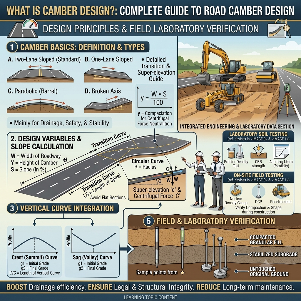
Camber Design refers to the process of providing a transverse slope across the road surface to allow rainwater to drain quickly from the pavement. The highest point of the road usually lies along the centerline, while both edges remain slightly lower.
This cross slope prevents water from collecting on the pavement surface. Efficient drainage protects the pavement structure, reduces hydroplaning, and improves vehicle control during wet weather.
Camber is usually expressed as:
- Percentage (%)
- Ratio (1 in n)
- Cross slope
For example:
- 2% Camber
- 1 in 50
- Cross slope = 2%
Although the numerical value appears small, it significantly influences pavement durability and driving safety.
Why Camber Design is Important
Water is one of the most destructive elements affecting pavement performance. Standing water weakens pavement layers, increases maintenance costs, and creates hazardous driving conditions.
An effective Camber Design offers several important benefits.
1. Rapid Surface Drainage
The transverse slope directs rainwater toward road shoulders and side drains before it infiltrates the pavement.
2. Increased Pavement Life
Dry pavement layers maintain their structural strength for a much longer period.
3. Improved Road Safety
Drivers experience better tire grip because water leaves the pavement surface quickly, reducing the risk of hydroplaning.
4. Reduced Maintenance Costs
Efficient drainage minimizes potholes, rutting, stripping, and surface cracking.
5. Better Riding Comfort
Properly designed camber prevents uneven water accumulation and maintains a smoother driving surface.
Objectives of Camber Design
Every highway engineer designs camber with several performance goals in mind.
Efficient Water Removal
The primary objective is to remove rainwater as quickly as possible.
Pavement Protection
Dry pavement layers resist deformation and structural failure more effectively than saturated materials.
Traffic Safety
Drivers require sufficient pavement friction during rainfall. Proper camber helps maintain tire contact with the road.
Structural Stability
Reduced water infiltration preserves the strength of the subgrade, sub-base, and base course.
Longer Service Life
Well-drained pavements require fewer repairs and remain serviceable for many years.
Engineering Principles of Camber Design
Engineers determine the appropriate camber based on pavement characteristics, rainfall intensity, traffic conditions, and drainage requirements.
Several engineering principles guide the design process.
Gravity-Assisted Drainage
Gravity naturally moves water from the highest point of the pavement toward the edges. Engineers use this principle to create effective cross slopes.
Surface Runoff
A steeper slope increases runoff speed. However, excessive slopes reduce driving comfort and vehicle stability.
Therefore, engineers balance drainage efficiency with user safety.
Vehicle Dynamics
Vehicles experience lateral forces while moving across sloped surfaces.
Proper camber minimizes these forces and provides a comfortable driving experience.
Pavement Material Characteristics
Different pavement materials respond differently to water exposure.
For example:
- Bituminous pavements drain water efficiently with relatively flatter cambers.
- Gravel roads require steeper cambers because water infiltrates their surfaces more easily.
Factors Affecting Camber Design
Several factors influence the selection of an appropriate camber value.
1. Type of Pavement
Different pavement surfaces require different cross slopes.
Typical pavement categories include:
- Cement concrete pavement
- Bituminous pavement
- Gravel pavement
- Earth roads
Rigid pavements usually require flatter cambers than unpaved roads.
2. Rainfall Intensity
Regions with heavy rainfall generally require slightly steeper cambers to improve drainage efficiency.
Areas with light rainfall often perform well with moderate cross slopes.
3. Surface Texture
Smooth pavement surfaces allow water to flow quickly.
Rough surfaces slow down runoff and therefore require greater slopes.
4. Traffic Speed
High-speed highways require carefully designed cambers to balance drainage with vehicle stability.
Excessive cross slopes may affect steering comfort at higher speeds.
5. Road Width
Wide carriageways require proper drainage planning to prevent water accumulation near the center of the road.
6. Climatic Conditions
Climate influences pavement behavior throughout its service life.
Engineers evaluate:
- Rainfall
- Snowfall
- Freeze-thaw cycles
- Temperature variations
before selecting suitable camber values.
Types of Camber Design
Several camber profiles are used in modern highway engineering.
The selection depends on pavement type, traffic volume, and construction requirements.
1. Straight Camber
Straight camber consists of two straight slopes meeting at the centerline.
Characteristics
- Simple geometry
- Easy construction
- Suitable for low-volume roads
- Economical solution
Applications
- Rural roads
- Village roads
- Low-speed roads
Diagram
        Crown
          ▲
         / \
        /   \
_______/     \_______
2. Parabolic Camber
Parabolic camber uses a smooth curved profile instead of straight slopes.
Advantages
- Better riding comfort
- Smooth water flow
- Improved appearance
- Reduced vehicle vibration
Applications
- National highways
- Expressways
- Urban arterial roads
Diagram
          Crown
            ▲
        ___/ \___
______/         \______
3. Composite Camber
Composite camber combines straight and curved sections.
The central portion generally follows a parabolic profile, while the outer portions remain straight.
Advantages
- Excellent drainage
- Comfortable driving
- Balanced construction cost
Applications
- High-volume highways
- Modern pavement systems
4. Barrel Camber
Barrel camber forms a rounded profile across the pavement width.
Although older road networks commonly used this profile, modern highway projects rarely adopt it because improved design methods now provide better drainage and riding quality.
Typical Camber Design Diagram
The following illustration shows the basic arrangement of a crowned roadway.
                Road Centre
                    ▲
                    │
        ← Water Flow │ Water Flow →
____________________/\____________________
                   /  \
                  /    \
                 /      \
        Shoulder        Shoulder
             ↓              ↓
         Side Drain     Side Drain
The highest point remains at the centerline, while rainwater flows toward both shoulders and enters the roadside drainage system.
General IRC, AASHTO, and ICE Recommendations
Although specific values vary according to project conditions, recognized highway engineering organizations share several common principles for effective Camber Design.
- Design cross slopes according to pavement type and climatic conditions.
- Ensure positive surface drainage under all weather conditions.
- Prevent water from ponding on the pavement surface.
- Coordinate camber with shoulder slopes and side drains.
- Maintain smooth transitions between straight sections and curves.
- Verify field construction using accurate surveying equipment.
- Inspect drainage performance regularly as part of pavement maintenance.
These principles help engineers deliver safer roads with improved durability and lower maintenance costs.
Key Takeaways
Camber Design plays a vital role in highway engineering by protecting pavement layers from water damage and improving road safety. A properly designed transverse slope removes rainwater efficiently, enhances skid resistance, and extends pavement life. Engineers select the appropriate camber after evaluating pavement type, rainfall intensity, traffic conditions, surface texture, and drainage requirements. Choosing the correct camber profile—whether straight, parabolic, composite, or barrel—ensures that the roadway performs efficiently throughout its design life while reducing future maintenance requirements.
Camber Design Calculation
Highway engineers calculate camber by considering pavement width, selected cross slope, pavement type, and local rainfall conditions. The objective is to provide sufficient drainage without compromising driving comfort or vehicle stability.
Basic Camber Formula
The relationship between pavement width and camber height is:
Camber Height (h) = (Road Width × Camber Percentage) ÷ 200
Where:
- h = Height of the crown above the pavement edge
- Road Width = Width of the carriageway
- Camber Percentage = Selected cross slope
Example Calculation
Assume:
- Carriageway Width = 7.0 m
- Camber = 2.5%
Camber Height
(7 × 2.5) ÷ 200
= 0.0875 m
= 87.5 mm
This means the centerline of the road should remain approximately 87.5 mm higher than each pavement edge.
Recommended Camber Values for Different Pavements
The required camber depends on pavement permeability, surface texture, and expected rainfall.
| Pavement Type | Recommended Camber |
|---|---|
| Cement Concrete Road | 1.5%–2.0% |
| Bituminous Road | 2.0%–3.0% |
| Gravel Road | 3.0%–4.0% |
| Earth Road | 4.0%–5.0% |
Why the Values Differ
- Concrete surfaces drain water efficiently, so they require a flatter cross slope.
- Asphalt pavements need a moderate slope for effective runoff.
- Gravel roads allow some water infiltration, so they need steeper cambers.
- Earth roads absorb water easily and therefore require the highest cross slopes.
Engineers always verify these values against project specifications, climate, and traffic conditions.
Camber Construction Methodology
Proper construction ensures that the designed camber performs as intended throughout the pavement’s service life.
Step 1: Setting Out
Surveyors establish the centerline, edge lines, and design elevations using total stations or automatic levels.
Step 2: Preparing the Subgrade
Construction crews grade and compact the subgrade according to the specified cross slope.
Step 3: Constructing the Sub-base
Workers spread, level, and compact the sub-base while maintaining the designed camber.
Step 4: Laying the Base Course
The base layer follows the same cross slope to provide uniform structural support.
Step 5: Constructing the Surface Course
Pavers place asphalt or concrete while maintaining the specified crown and transverse slope.
Step 6: Final Surface Verification
Engineers measure cross slopes and elevations before opening the road to traffic.
Equipment Used in Camber Construction
Modern road projects use specialized equipment to achieve accurate camber profiles.
- Motor Grader
- Asphalt Paver
- Concrete Paver
- Vibratory Roller
- Pneumatic Roller
- Automatic Level
- Total Station
- Straight Edge
- Digital Level
- Measuring Staff
Proper calibration of surveying instruments improves construction accuracy.
Quality Control in Camber Construction
Quality control begins before construction and continues until project completion.
Survey Verification
Engineers verify centerline elevations and edge levels at regular intervals.
Cross Slope Measurement
Teams measure the transverse slope using digital levels, templates, or surveying equipment.
Surface Evenness
Engineers inspect the pavement surface for depressions or irregularities that may retain water.
Compaction Testing
Each pavement layer undergoes density testing before the next layer begins.
Drainage Inspection
Water flow tests confirm that runoff reaches side drains without ponding on the pavement.
Common Mistakes in Camber Design
Several construction and design errors reduce the effectiveness of camber.
Inadequate Cross Slope
A flat pavement allows water to accumulate on the surface.
Excessive Camber
An overly steep cross slope reduces driving comfort and may affect vehicle stability.
Poor Construction Accuracy
Incorrect grading creates low spots that trap water.
Improper Drainage Design
Blocked shoulders or undersized drains prevent water from leaving the roadway.
Ignoring Local Climate
Selecting the same camber for all climates may lead to drainage problems in regions with heavy rainfall.
Lack of Maintenance
Sediment and vegetation often block side drains if maintenance teams neglect routine inspections.
Engineering Best Practices for Camber Design
Successful highway projects follow proven engineering practices.
- Conduct detailed topographic surveys before design.
- Evaluate local rainfall and drainage patterns.
- Select camber values according to pavement type.
- Coordinate pavement slopes with shoulder and side drain gradients.
- Maintain consistent cross slopes throughout construction.
- Verify elevations using calibrated survey equipment.
- Perform regular drainage inspections after project completion.
- Repair surface depressions before they develop into potholes.
- Include maintenance planning in the overall pavement management strategy.
Practical Recommendations
Civil Engineers
- Check cross slopes during every construction stage.
- Review drainage plans together with pavement drawings.
- Monitor construction tolerances closely.
- Document field measurements for quality assurance.
Contractors
- Train equipment operators to maintain the specified crown profile.
- Use accurate surveying equipment throughout construction.
- Avoid placing pavement during unsuitable weather conditions.
- Inspect finished surfaces immediately after paving.
Engineering Students
- Understand how camber influences pavement drainage.
- Practice cross-section calculations.
- Learn standard surveying methods for slope measurement.
- Visit highway projects to observe field construction techniques.
Practical Applications of Camber Design
Camber plays an important role in different transportation facilities.
National Highways
Highways require carefully designed cross slopes to handle heavy traffic and intense rainfall.
Urban Roads
City streets depend on camber to direct runoff into stormwater drainage systems.
Airport Runways
Runways use transverse slopes to remove water quickly while maintaining aircraft safety.
Parking Areas
Large parking lots include gentle cross slopes to prevent water accumulation.
Industrial Roads
Industrial facilities use proper camber to improve pavement durability under heavy truck traffic.
Simple Camber Water Flow Diagram
             Road Centre (Highest Point)
                     ▲
                     │
      Water Flow ←   │   → Water Flow
_____________________/ \_____________________
                    /   \
                   /     \
                  /       \
           Shoulder      Shoulder
               ↓              ↓
         Side Drain      Side Drain
This arrangement ensures that rainwater leaves the pavement surface quickly and enters the drainage system without damaging the road structure.
General Discussion on IRC, AASHTO, and ICE Recommendations
Leading highway engineering organizations promote similar principles for effective pavement drainage.
General recommendations include:
- Select cross slopes according to pavement type and climatic conditions.
- Ensure rapid removal of rainwater from the carriageway.
- Coordinate pavement camber with shoulder slopes and drainage channels.
- Maintain smooth transitions between tangents and horizontal curves.
- Inspect completed surfaces using precise surveying equipment.
- Monitor pavement drainage throughout the service life.
- Include preventive maintenance in highway asset management programs.
Following these principles helps engineers build safer and longer-lasting roads.
Frequently Asked Questions (FAQs)
1. What is camber in road engineering?
Camber is the transverse slope provided across the road surface to drain rainwater toward the shoulders and side drains.
2. Why is camber design important?
Camber prevents water accumulation, protects pavement layers, improves skid resistance, and extends pavement life.
3. Which pavement requires the highest camber?
Earth roads generally require the highest camber because water easily penetrates their surface.
4. What is the difference between camber and superelevation?
Camber provides drainage on straight sections, while superelevation counteracts centrifugal force on horizontal curves.
5. How do engineers calculate camber height?
Engineers calculate camber height using pavement width and the selected cross slope percentage.
6. Can excessive camber create safety problems?
Yes. Excessive camber may reduce driving comfort, increase lateral vehicle movement, and create steering difficulties.
7. Which equipment helps construct accurate camber?
Motor graders, asphalt pavers, automatic levels, total stations, digital levels, and rollers help achieve accurate camber profiles.
8. Does climate affect camber design?
Yes. Areas with heavy rainfall often require steeper cross slopes than dry regions to improve drainage.
9. How often should engineers inspect camber?
Engineers should inspect pavement drainage regularly, especially after heavy rainfall and during routine highway maintenance.
10. What happens if a road has insufficient camber?
Insufficient camber causes water ponding, accelerates pavement deterioration, increases hydroplaning risk, and raises maintenance costs.
Conclusion
Camber Design remains one of the most essential aspects of highway engineering because it directly influences pavement performance, road safety, and maintenance costs. A well-designed camber allows rainwater to leave the pavement quickly, protects the structural layers from moisture damage, and improves vehicle traction during wet conditions. Engineers must evaluate pavement type, traffic volume, rainfall intensity, surface texture, and local environmental conditions before selecting an appropriate cross slope. Accurate surveying, quality construction practices, and regular maintenance ensure that the designed camber continues to function effectively throughout the road’s service life. Whether designing a rural road, an urban street, or a high-speed expressway, proper Camber Design contributes to durable infrastructure, lower lifecycle costs, and safer transportation networks. By applying established engineering principles and following recognized guidance from organizations such as IRC, AASHTO, and ICE, engineers, contractors, and students can deliver road projects that perform reliably for many years.

Kamran Malik is a passionate civil engineering writer and researcher who specializes in construction, transportation, structural engineering, and infrastructure topics. Through his articles on CivilEngineerings.com, he simplifies complex engineering concepts and shares practical insights, industry trends, and educational resources for students, professionals, and engineering enthusiasts.