
Introduction
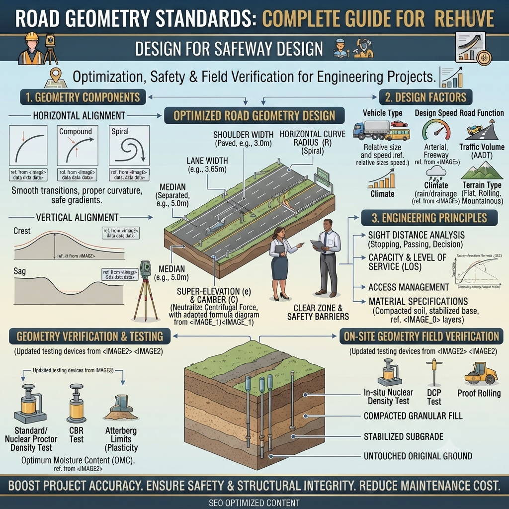
Roads are more than strips of pavement connecting places. Every highway, expressway, rural road, or city street is carefully designed using engineering principles that ensure safety, efficiency, comfort, and long-term performance. One of the most important aspects of highway engineering is Road Geometry Standards, which define how roads should be aligned horizontally and vertically, how wide lanes should be, how curves are designed, and how drivers can safely navigate different roadway conditions.
Whether a road carries a few hundred vehicles each day or serves as a major expressway handling thousands of vehicles every hour, proper geometric design directly influences traffic flow, accident rates, construction costs, and maintenance requirements. Poor geometric design can result in limited visibility, unsafe curves, vehicle instability, drainage problems, and increased operating costs.
For civil engineering students, highway engineers, contractors, consultants, and infrastructure planners, understanding Road Geometry Standards is essential for designing transportation systems that remain safe and functional throughout their service life.
This comprehensive guide explains the fundamental principles of geometric road design, discusses major design elements, introduces practical engineering calculations, and shares real-world examples to help readers understand how these standards are applied in modern highway engineering.
What are Road Geometry Standards?
Road Geometry Standards are engineering guidelines used to determine the physical dimensions and layout of roads and highways. These standards define how road alignments, curves, gradients, lane widths, shoulders, medians, and intersections should be designed to provide safe and efficient transportation.
Rather than focusing only on pavement materials or structural strength, geometric design considers how drivers interact with the roadway. Vehicle speed, stopping distance, turning capability, visibility, and traffic volume all influence the final road geometry.
Purpose
The primary purpose of geometric standards is to create roads that:
- Improve road safety
- Enhance driving comfort
- Reduce travel time
- Increase traffic capacity
- Minimize accident risk
- Reduce vehicle operating costs
- Support future traffic growth
Why Road Geometry Standards Matter
Modern transportation systems depend on consistent geometric design because drivers subconsciously expect predictable road conditions. When lane widths, curves, slopes, or intersections suddenly change without proper transitions, the likelihood of crashes increases.
Proper geometric design also improves:
- Fuel efficiency
- Traffic operations
- Emergency vehicle movement
- Freight transportation
- Highway maintenance
- Stormwater drainage
- Long-term pavement performance
Objectives of Road Geometry Standards
Road geometry is developed to satisfy several engineering objectives simultaneously.
1. Ensure Road Safety
Safety remains the highest priority during highway design. Proper alignment reduces collision risks by improving visibility and providing sufficient reaction time.
2. Improve Traffic Efficiency
Efficient geometric layouts minimize congestion, reduce delays, and increase roadway capacity.
3. Enhance Driving Comfort
Smooth curves and gradual changes in elevation reduce driver fatigue and improve passenger comfort.
4. Reduce Construction Costs
Well-planned alignments minimize unnecessary excavation, embankment construction, bridge structures, and retaining walls.
5. Support Future Development
Roads should accommodate increasing traffic demand without requiring major reconstruction within a short period.
Major Elements of Road Geometry Standards
Road geometry consists of several interconnected design components.
                 ROAD GEOMETRY
                       │
 ┌──────────────┬───────────────┬───────────────┐
 │              │               │
Horizontal   Vertical      Cross Section
Alignment    Alignment      Elements
 │              │               │
Curves      Gradients      Lane Width
Tangents    Summit Curve   Shoulder
Transition  Valley Curve   Median
Horizontal Alignment
Horizontal alignment defines the road’s path when viewed from above. It consists of straight sections connected by curves that allow vehicles to change direction safely.
Components
- Tangents
- Circular curves
- Spiral transition curves
- Compound curves
- Reverse curves
Working Principle
A properly designed curve balances centrifugal force with vehicle speed using an appropriate radius and superelevation.
Practical Example
On a mountainous highway, designers introduce spiral transition curves before sharp bends. These transitions gradually increase curvature, allowing drivers to adjust steering smoothly rather than making sudden movements.
Advantages
- Improves driving comfort
- Reduces skid risk
- Enhances vehicle stability
- Improves traffic flow
Limitations
- Requires more land
- May increase construction cost
- Difficult to implement in densely developed urban areas
Vertical Alignment
Vertical alignment represents the road profile along its length.
It includes:
- Gradients
- Crest curves
- Sag curves
      Crest Curve

         /\
        /  \
_______/    \_______


       Sag Curve

_______      _______
       \    /
        \__/
Engineering Purpose
Vertical alignment ensures:
- Comfortable vehicle movement
- Proper drainage
- Adequate sight distance
- Reduced fuel consumption
- Stable heavy vehicle operation
Types of Gradients
- Ruling Gradient
- Limiting Gradient
- Exceptional Gradient
- Minimum Gradient
Each gradient is selected according to terrain, traffic volume, and design speed.
Practical Example
A highway crossing rolling terrain often uses ruling gradients to maintain safe truck speeds while minimizing excavation.
Cross-Sectional Elements
The road cross-section defines the roadway width and supporting features.
 Shoulder  Lane   Lane   Median   Lane   Lane  Shoulder
 -------------------------------------------------------
                Carriageway
Main Components
Lane Width
Lane width depends on:
- Vehicle size
- Traffic volume
- Design speed
Wider lanes improve safety but require more right-of-way.
Shoulder
Shoulders provide space for:
- Emergency stopping
- Disabled vehicles
- Maintenance activities
- Drainage support
Median
Medians separate opposing traffic streams and reduce the likelihood of head-on collisions.
Side Slopes
Proper side slopes improve embankment stability and reduce erosion.
Drainage
Cross slopes help remove rainwater quickly, protecting the pavement from moisture damage.
Sight Distance
Sight distance is one of the most critical aspects of Road Geometry Standards.
It represents the distance a driver must be able to see ahead to react safely.
Types
Stopping Sight Distance (SSD)
Distance required for:
- Driver perception
- Reaction
- Vehicle braking
Overtaking Sight Distance (OSD)
Required when vehicles safely pass slower traffic.
Intermediate Sight Distance
Used where overtaking distance cannot be fully achieved.
Intersection Sight Distance
Ensures drivers can observe approaching vehicles before entering intersections.
Practical Example
A rural highway with frequent agricultural vehicles requires longer overtaking sight distance than a congested urban road.
Superelevation
Superelevation is the upward slope provided on the outer edge of a horizontal curve.
Its purpose is to counteract centrifugal force.
Straight Road

──────────────

Curved Road

      /
_____/________
Benefits
- Improves vehicle stability
- Reduces skidding
- Minimizes overturning risk
- Enhances passenger comfort
Basic Formula
[
e + f = \frac{V^2}{127R}
]
Where:
- e = Superelevation
- f = Side friction factor
- V = Design speed (km/h)
- R = Curve radius (m)
Example Calculation
Given:
- Design Speed = 80 km/h
- Radius = 250 m
[
\frac{80^2}{127 \times 250}
0.20
]
If the allowable side friction factor is 0.08:
[
e = 0.20 – 0.08 = 0.12
]
Therefore, the required superelevation is approximately 12%. In practice, agencies often limit maximum superelevation to lower values based on climate, vehicle mix, and applicable standards, so the designer may instead increase the curve radius or reduce the design speed.
Transition Curves
Transition curves gradually connect a straight section with a circular curve.
Without transition curves:
- Steering changes become abrupt.
- Passenger discomfort increases.
- Vehicle stability decreases.
Common Types
- Spiral
- Clothoid
- Cubic parabola
Working Principle
The radius changes gradually from infinity (straight road) to the design curve radius.
Straight
──────────────╮
              ╰──────◜
                    Curve
Key Design Considerations
When applying Road Geometry Standards, engineers evaluate multiple factors before finalizing the road layout:
- Design speed: Higher speeds require flatter curves, longer sight distances, and gentler gradients.
- Terrain: Plain, rolling, mountainous, and steep terrain demand different alignment strategies.
- Traffic characteristics: Vehicle mix, heavy truck percentage, and projected traffic growth influence lane widths and curve design.
- Climate: Rainfall, snow, wind, and temperature affect drainage, superelevation, and pavement performance.
- Safety requirements: Adequate visibility, forgiving roadsides, and consistent geometry reduce crash risk.
- Environmental constraints: Rivers, forests, wetlands, and protected habitats may limit alignment options.
- Construction and maintenance costs: Designers seek a balance between safety, performance, and economic feasibility.
Advantages of Road Geometry Standards
- Improve road safety and reduce accident rates.
- Provide consistent driving conditions across the road network.
- Increase traffic capacity and operational efficiency.
- Enhance driver comfort by minimizing sudden changes in alignment.
- Improve pavement durability through better drainage and smoother vehicle loading.
- Reduce long-term maintenance costs with well-planned geometric layouts.
- Support sustainable transportation planning and future road expansion.
Limitations of Road Geometry Standards
- Difficult terrain may restrict ideal geometric layouts.
- Land acquisition can limit alignment improvements in urban areas.
- Higher design standards often increase initial construction costs.
- Existing roads may require compromises during widening or rehabilitation.
- Environmental and social constraints may necessitate design adjustments beyond purely geometric considerations.
Construction Process for Implementing Road Geometry Standards
Applying Road Geometry Standards begins long before construction equipment arrives on site. Every stage—from planning to maintenance—must follow engineering principles to ensure the finished roadway is safe, economical, and durable.
1. Planning
The planning phase identifies transportation needs and evaluates possible routes.
Key Activities
- Traffic demand forecasting
- Land use analysis
- Economic feasibility studies
- Environmental impact assessment
- Preliminary cost estimation
- Stakeholder consultation
Practical Example:
When planning a bypass around a growing city, engineers compare several route options to minimize travel time while reducing impacts on nearby communities and environmentally sensitive areas.
2. Surveying
Accurate surveys provide the foundation for geometric design.
Common surveying activities include:
- Topographic surveys
- Route reconnaissance
- GPS surveys
- Total Station measurements
- Drone mapping
- LiDAR surveys
- Geotechnical investigations
Survey Layout (ASCII Diagram)
       BM
       ▲
       │
P1────P2────P3────P4
 │              │
Road Centerline
Survey data defines existing ground levels, natural drainage, utilities, and obstacles.
3. Geometric Design
Using survey information, highway engineers design:
- Horizontal alignment
- Vertical alignment
- Cross-sectional elements
- Intersections
- Roundabouts
- Interchanges
- Service roads
- Drainage systems
Design software such as Civil 3D, OpenRoads Designer, and MX Road is commonly used to model the road corridor and optimize alignments.
4. Material Selection
Material selection influences both pavement performance and long-term maintenance costs.
Common Materials
| Material | Application |
|---|---|
| Bitumen | Asphalt pavement binder |
| Cement | Concrete pavements and structures |
| Aggregates | Base, sub-base, and asphalt mixes |
| Sand | Bedding and concrete |
| Geotextiles | Soil separation and filtration |
| Geogrids | Reinforcement of weak subgrades |
| Fly Ash | Soil stabilization |
| Lime | Clay stabilization |
| Crushed Stone | Base course |
| Concrete | Rigid pavements and drainage structures |
Material selection depends on climate, traffic loading, subgrade conditions, and project budget.
5. Earthwork
Earthwork shapes the roadway according to the approved geometric design.
Major activities include:
- Clearing and grubbing
- Excavation
- Embankment construction
- Soil stabilization
- Compaction
- Slope protection
Proper compaction minimizes future settlement and helps maintain the designed road geometry.
6. Pavement Construction
Flexible Pavement Layers
 Asphalt Surface Course
------------------------
 Binder Course
------------------------
 Base Course
------------------------
 Sub-base
------------------------
 Compacted Subgrade
Rigid Pavement
 Concrete Slab
------------------------
 Base Course
------------------------
 Sub-base
------------------------
 Compacted Soil
Proper geometric control is maintained throughout construction to ensure the finished road matches design elevations, cross slopes, and alignment.
7. Quality Control
Quality control verifies that construction complies with design specifications.
Common Tests
| Test | Purpose |
|---|---|
| CBR Test | Evaluate subgrade strength |
| Standard/Modified Proctor Test | Determine optimum moisture and maximum dry density |
| Marshall Stability Test | Assess asphalt mix performance |
| Slump Test | Check concrete workability |
| Density Test | Verify field compaction |
| Core Test | Measure pavement thickness and density |
| Plate Load Test | Evaluate bearing capacity |
Routine inspection ensures lane widths, gradients, superelevation, and pavement levels remain within acceptable tolerances.
8. Maintenance
Road geometry must be preserved throughout the road’s service life.
Maintenance activities include:
- Pavement resurfacing
- Shoulder repairs
- Drainage cleaning
- Guardrail replacement
- Signage maintenance
- Vegetation control
- Pavement marking renewal
- Slope stabilization
Ignoring maintenance can reduce sight distance, weaken drainage, and compromise roadway safety.
Practical Applications of Road Geometry Standards
These standards are essential across a wide range of transportation projects.
Highways
High-speed highways require generous curve radii, long stopping sight distances, and carefully designed interchanges.
Expressways
Controlled-access expressways prioritize uninterrupted traffic flow with consistent lane widths and medians.
Urban Roads
Urban streets accommodate pedestrians, cyclists, buses, and frequent intersections, requiring balanced geometric design.
Rural Roads
Rural roads emphasize safe overtaking opportunities, adequate shoulders, and improved visibility.
Airport Roads
Access roads serving airports must accommodate heavy traffic volumes and large commercial vehicles.
Industrial Roads
Industrial facilities often require wider turning radii and stronger pavement structures for heavy trucks.
Smart Cities
Road geometry supports dedicated bus lanes, cycling infrastructure, intelligent traffic systems, and autonomous vehicle operations.
Equipment Used in Geometric Road Construction
Common construction equipment includes:
- Excavators
- Bulldozers
- Motor Graders
- Wheel Loaders
- Asphalt Pavers
- Concrete Pavers
- Vibratory Rollers
- Pneumatic Tyred Rollers
- Water Tankers
- Survey Instruments
- GPS Machine Control Systems
- Total Stations
- Drones
- LiDAR Scanners
Each machine contributes to achieving the required alignment, levels, and cross-sectional dimensions.
Best Practices for
Engineers
- Select an appropriate design speed based on terrain and expected traffic.
- Verify survey data before finalizing alignments.
- Design consistent horizontal and vertical geometry to avoid unexpected changes.
- Provide adequate drainage and erosion control.
- Perform independent design reviews before construction.
Contractors
- Establish reliable survey control before earthwork begins.
- Monitor compaction and layer thickness continuously.
- Check superelevation and cross slopes during paving.
- Calibrate equipment regularly.
- Maintain accurate construction records.
Students
- Develop a strong understanding of geometric design fundamentals.
- Practice interpreting highway plans and cross-sections.
- Learn commonly used highway design software.
- Study the relationship between design speed, curve radius, and sight distance.
Consultants
- Coordinate geometric design with geotechnical, drainage, structural, and traffic engineering teams.
- Consider future expansion requirements.
- Balance safety, cost, and environmental impacts when evaluating alternatives.
Common Mistakes and How to Avoid Them
Inadequate Sight Distance
Cause: Poor alignment or roadside obstructions.
Consequence: Increased collision risk.
Solution: Design for adequate stopping and decision sight distance and keep visibility zones clear.
Incorrect Superelevation
Cause: Construction inaccuracies or unsuitable design assumptions.
Consequence: Vehicle instability, especially on curves.
Solution: Verify calculations, stake out transitions accurately, and inspect during construction.
Poor Drainage
Cause: Insufficient cross slope or blocked drainage systems.
Consequence: Water accumulation, pavement deterioration, and hydroplaning.
Solution: Design effective drainage, maintain ditches and inlets, and inspect after heavy rainfall.
Ignoring Future Traffic Growth
Cause: Underestimating long-term demand.
Consequence: Premature congestion and costly upgrades.
Solution: Use realistic traffic forecasts and consider phased expansion.
Inconsistent Alignment
Cause: Abrupt changes in curve radius or gradient.
Consequence: Driver discomfort and increased crash potential.
Solution: Maintain design consistency and use transition curves where appropriate.
Sustainability in Road Geometry Design
Sustainable practices improve long-term performance while reducing environmental impacts.
Examples include:
- Recycled asphalt pavement (RAP)
- Recycled concrete aggregates
- Warm-mix asphalt
- Low-carbon concrete
- Rainwater harvesting
- Bioswales and vegetated drainage channels
- Energy-efficient LED roadway lighting
- Erosion and sediment control measures
- Wildlife crossings
- Climate-resilient drainage systems
Sustainable geometric design also minimizes unnecessary earthwork and preserves natural landscapes where practical.
Modern Technologies
Modern highway engineering increasingly relies on digital tools to improve accuracy and efficiency.
Building Information Modeling (BIM)
BIM enables multidisciplinary coordination throughout design, construction, and asset management.
Geographic Information Systems (GIS)
GIS supports corridor selection, environmental analysis, and transportation planning.
LiDAR
LiDAR rapidly captures highly accurate terrain data for route design and earthwork calculations.
Drones
Drones assist with surveys, construction monitoring, progress reporting, and inspections.
Artificial Intelligence (AI)
AI analyzes traffic data, predicts maintenance needs, and optimizes geometric design alternatives.
Machine Control
GPS-guided construction equipment improves grading accuracy and reduces rework.
IoT Sensors
Embedded sensors monitor pavement performance, traffic, and environmental conditions in real time.
Digital Twins
Digital twins create virtual representations of transportation assets, supporting lifecycle management and predictive maintenance.
General Overview of Engineering Standards
Road geometry is guided by internationally recognized engineering organizations. While specific requirements vary by country and project, designers commonly reference guidance from:
- IRC (Indian Roads Congress): Provides recommendations for geometric design, road safety, and highway engineering practices in India.
- AASHTO (American Association of State Highway and Transportation Officials): Widely recognized for guidance on highway geometric design, often referred to as the “Green Book.”
- ASTM International: Publishes standards for testing materials used in road construction and quality control.
- FHWA (Federal Highway Administration): Offers technical guidance on highway planning, safety, and geometric design in the United States.
- ISO (International Organization for Standardization): Develops international standards that support quality management, surveying, and infrastructure-related processes.
- ICE (Institution of Civil Engineers): Shares engineering best practices, technical knowledge, and professional guidance for civil infrastructure projects.
Engineers should always follow the latest standards and regulations applicable to the country or agency responsible for the project.
Frequently Asked Questions (FAQs)
1. What are Road Geometry Standards?
Road Geometry Standards are engineering guidelines that define the physical layout of roads, including alignment, curves, gradients, lane widths, shoulders, and sight distances. Their primary purpose is to provide safe, efficient, and comfortable travel while balancing construction costs, environmental constraints, and long-term maintenance needs. Consistent application of these standards improves traffic flow and reduces crash risk.
2. Why is geometric design important in highway engineering?
Geometric design directly affects road safety, operating speed, driver comfort, and traffic capacity. Proper alignment, adequate sight distance, and well-designed curves help drivers react safely to changing conditions. Good geometry also improves drainage, reduces pavement distress, and supports efficient transportation over the road’s service life.
3. What is the difference between horizontal and vertical alignment?
Horizontal alignment defines the roadway path when viewed from above, using tangents and curves to change direction. Vertical alignment describes changes in elevation along the road profile through gradients, crest curves, and sag curves. Both must work together to provide safe visibility, comfortable driving, and efficient drainage.
4. How does superelevation improve road safety?
Superelevation raises the outer edge of a curve to counteract centrifugal force acting on vehicles. This reduces the likelihood of skidding and overturning while improving vehicle stability and passenger comfort. Correct superelevation must be coordinated with curve radius, design speed, and local climatic conditions.
5. What factors influence road geometry design?
Key factors include design speed, terrain, traffic volume, vehicle characteristics, climate, drainage requirements, environmental constraints, land availability, and future traffic growth. Engineers also consider economic feasibility, construction practicality, and maintenance requirements before finalizing the alignment.
6. Which software is commonly used for geometric road design?
Engineers frequently use Autodesk Civil 3D, Bentley OpenRoads Designer, MX Road, and other corridor modeling software. These tools support terrain modeling, alignment design, earthwork calculations, cross-section generation, and visualization, improving design accuracy and coordination across project teams.
7. How is quality controlled during road construction?
Quality control involves field inspections and laboratory testing throughout construction. Tests such as CBR, Proctor, Marshall Stability, density, slump, and core tests verify that materials and workmanship meet project requirements. Survey checks ensure that finished alignments, elevations, lane widths, and cross slopes conform to the approved design.
8. What role do Road Geometry Standards play in smart transportation?
Modern transportation systems rely on consistent geometric design to support intelligent traffic management, connected vehicles, and autonomous driving technologies. Accurate road geometry also improves digital mapping, sensor performance, and infrastructure monitoring, making future transportation networks safer and more efficient.
9. How do Road Geometry Standards support sustainability?
Well-designed road geometry minimizes unnecessary earthwork, improves drainage, reduces vehicle fuel consumption through smoother alignments, and extends pavement life. Incorporating recycled materials, climate-resilient drainage, and environmentally sensitive route selection further reduces the environmental footprint of transportation infrastructure.
Conclusion
Road Geometry Standards provide the engineering framework needed to design roads that are safe, efficient, durable, and sustainable. From horizontal and vertical alignment to sight distance, superelevation, and cross-sectional design, every geometric element influences traffic operations, construction costs, maintenance requirements, and overall road safety. Modern technologies such as BIM, GIS, LiDAR, AI, and Digital Twins are transforming how engineers plan and manage transportation infrastructure, while internationally recognized guidance from organizations like IRC, AASHTO, ASTM, FHWA, ISO, and ICE helps promote consistent design practices. By understanding and applying these principles, engineers, contractors, students, and consultants can deliver transportation projects that meet today’s demands and remain reliable for decades to come.
