
Introduction
The Plate Load Test ranks among the most reliable in-situ geotechnical tests for evaluating the bearing capacity and settlement characteristics of soil. Civil engineers, highway engineers, and geotechnical consultants frequently perform this test before constructing roads, bridges, industrial buildings, retaining walls, and shallow foundations. Unlike laboratory soil tests, the Plate Load Test measures soil behavior under actual field conditions, which makes the results highly dependable for engineering design.
A well-executed Plate Load Test helps engineers determine whether the existing ground can safely support the proposed structure. It also provides valuable information about soil deformation, allowable bearing pressure, and the modulus of subgrade reaction (k-value), which plays a significant role in rigid pavement design.
Whether you are a civil engineering student, a site engineer, or a highway contractor, understanding the Plate Load Test improves your ability to make informed foundation and pavement decisions. This guide explains the theory, objectives, equipment, procedure, engineering concepts, and practical applications using simple language and professional engineering practices.
What is the PLT?
The Plate Load Test is an in-situ field test used to evaluate the load-bearing capacity and settlement behavior of soil by applying controlled loads to a rigid steel plate placed on the prepared ground surface.
Engineers gradually increase the applied load while measuring the resulting settlement. The relationship between load and settlement helps determine whether the soil can safely support the proposed structure.
Unlike laboratory testing, this method reflects actual site conditions because it evaluates undisturbed soil in the field.
Simple Definition
A Plate Load Test measures how much load the ground can support before excessive settlement occurs.
Why is the PLT Important?
Every engineering structure transfers its load to the underlying soil. Weak soil can cause excessive settlement, structural damage, and even foundation failure.
The Plate Load Test provides field data that helps engineers:
- Estimate safe bearing capacity.
- Evaluate settlement characteristics.
- Design shallow foundations.
- Design rigid pavements.
- Verify ground improvement works.
- Reduce construction risks.
- Improve project safety.
For highway projects, engineers often perform the test before constructing concrete pavements, toll plazas, industrial roads, container yards, and airport runways.
Objectives of the PLT
The primary purpose of the Plate Load Test extends beyond measuring soil strength. Engineers use it to evaluate several important geotechnical properties.
Main Objectives
- Determine ultimate bearing capacity.
- Calculate allowable bearing pressure.
- Measure immediate settlement.
- Evaluate load-settlement behavior.
- Determine the modulus of subgrade reaction (k-value).
- Assess the effectiveness of soil stabilization.
- Verify design assumptions made during geotechnical investigations.
Practical Importance
Suppose a contractor plans to construct a warehouse on reclaimed land. Laboratory reports indicate medium-dense sandy soil, but the design team needs field verification before construction.
A Plate Load Test confirms whether the existing soil can safely support the proposed foundation without excessive settlement.
Engineering Principles Behind the PLT
The Plate Load Test works on a simple engineering principle.
When an external load acts on soil, the soil particles rearrange and compress. As the applied load increases, settlement also increases.
Engineers monitor this relationship carefully.
The resulting load-settlement curve provides valuable information about soil behavior under different loading conditions.
Engineering Concepts
The test evaluates:
- Stress distribution
- Soil deformation
- Elastic settlement
- Plastic settlement
- Bearing resistance
- Failure characteristics
Soil Response
Different soils respond differently under loading.
Dense Sand
- Small settlement
- High bearing capacity
- Rapid stabilization
Loose Sand
- Larger settlement
- Lower bearing capacity
- Greater particle rearrangement
Clay
- Slow settlement
- Time-dependent deformation
- Lower drainage capacity
Understanding these responses helps engineers select appropriate foundation systems.
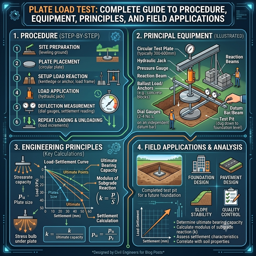
Equipment Required for the Plate Load Test
Accurate equipment ensures reliable test results.
Essential Equipment
- Circular or square steel bearing plate
- Hydraulic jack
- Reaction frame or reaction beam
- Kentledge (counterweight) or reaction piles
- Load cell or proving ring
- Dial gauges
- Datum beam
- Measuring scale
- Excavation tools
- Spirit level
- Steel ruler
Typical Plate Sizes
The most commonly used steel plates include:
- 300 mm × 300 mm
- 450 mm × 450 mm
- 600 mm × 600 mm
- Circular plates of equivalent diameter
The plate size depends on soil type, foundation dimensions, and project specifications.
Test Site Preparation
Proper preparation improves test accuracy and repeatability.
Site Selection
Engineers select locations that represent actual foundation conditions.
They avoid:
- Disturbed ground
- Filled pits
- Recently excavated areas
- Utility trenches
Excavation
The excavation depth depends on the proposed foundation level.
The base of the pit should remain:
- Clean
- Level
- Firm
- Undisturbed
Loose material must be removed before placing the steel plate.
Plate Load Test Procedure Step by Step
Step 1 – Selecting the Test Location
Engineers choose the location based on:
- Foundation layout
- Soil investigation reports
- Borehole data
- Project requirements
The selected location should represent the average site conditions.
Step 2 – Excavation and Surface Preparation
Workers excavate the pit to the required foundation depth.
Engineers then:
- Remove loose soil.
- Level the base.
- Check horizontal alignment.
- Ensure firm contact between soil and plate.
A smooth surface improves load transfer.
Step 3 – Positioning the Steel Plate
The steel bearing plate is carefully placed at the center of the prepared surface.
Engineers verify:
- Plate alignment
- Full contact with soil
- Horizontal position
Any gap beneath the plate can affect the test results.
Step 4 – Installing the Loading System
The loading arrangement consists of:
- Hydraulic jack
- Reaction beam or reaction frame
- Counterweight or reaction piles
- Dial gauges
The datum beam supporting the dial gauges remains independent of the loading system to prevent measurement errors.
Step 5 – Applying the Load
The hydraulic jack applies the load in equal increments.
After each load increment:
- The load remains constant.
- Engineers observe settlement.
- Dial gauge readings are recorded at regular intervals.
Loading continues until:
- Design load is reached, or
- Soil failure occurs, or
- Excessive settlement develops.
Step 6 – Recording Settlement
Settlement readings are typically recorded:
- Immediately after loading
- At 1 minute
- 2 minutes
- 4 minutes
- 8 minutes
- 15 minutes
- 30 minutes
- 60 minutes
Additional readings may be taken depending on soil type and project specifications.
Consistent observation improves result accuracy.
Step 7 – Continuing Until Failure or Maximum Load
The loading process continues until one of the following occurs:
- Ultimate bearing capacity is reached.
- Settlement increases rapidly.
- Maximum specified load is achieved.
- Project requirements are satisfied.
After completing the loading sequence, engineers gradually remove the load while monitoring soil rebound.
Plate Load Test Field Diagram
Typical Test Arrangement
                   Reaction Beam / Kentledge
        =========================================
                     ▲
                     │
              Hydraulic Jack
                     │
             ┌─────────────────┐
             │   Steel Plate   │
             └─────────────────┘
        =============================
          Prepared Soil Surface
        =============================
              Natural Ground

     Datum Beam
 ───────────────────────────────
      │                   │
 Dial Gauge          Dial Gauge
Load Transfer Mechanism
 Applied Load
      ↓
 ┌────────────┐
 │ Steel Plate│
 └────────────┘
      ↓↓↓↓↓↓↓
  Stress Distribution
      ↓↓↓↓↓↓↓
 Compacted Soil Layer
      ↓↓↓↓↓↓↓
 Natural Subsoil
These simplified diagrams illustrate how the applied load transfers through the steel plate into the supporting soil while settlement is measured independently by the dial gauges.
Practical Example
A highway authority plans to construct a rigid concrete pavement for a logistics terminal. The design requires confirmation of the subgrade’s support characteristics before finalizing the pavement thickness.
Engineers conduct a Plate Load Test using a 600 mm steel plate. They apply the load in controlled increments and record the corresponding settlement values. The resulting load-settlement curve indicates adequate bearing capacity and an acceptable modulus of subgrade reaction. Based on these findings, the design team confirms the pavement thickness without requiring expensive ground improvement measures. This field verification saves both construction time and project costs while improving confidence in the final design.
Key Takeaways
The Plate Load Test provides a direct assessment of soil behavior under actual field conditions. By measuring the relationship between applied load and settlement, engineers can evaluate bearing capacity, settlement characteristics, and subgrade performance with greater confidence than laboratory testing alone. Careful site preparation, accurate equipment setup, and systematic loading procedures ensure dependable results. These early stages form the foundation for safe and economical foundation and pavement design, making the Plate Load Test one of the most valuable in-situ investigations in civil and highway engineering.
Interpretation of Plate Load Test Results
Completing the field test marks the beginning of the engineering evaluation. Engineers study the recorded load and settlement values to understand how the soil behaves under increasing pressure. A proper interpretation helps determine whether the soil can safely support the proposed structure.
A gradual increase in settlement with increasing load generally indicates stable soil behavior. A sudden increase in settlement often signals soil failure or the approach to the ultimate bearing capacity.
Parameters Obtained from the Test
The Plate Load Test helps engineers determine:
- Ultimate bearing capacity
- Safe or allowable bearing capacity
- Settlement characteristics
- Elastic deformation
- Modulus of subgrade reaction (k-value)
- Load-settlement relationship
These parameters guide foundation and pavement design while reducing the uncertainty associated with soil behavior.
Load–Settlement Curve
The load–settlement curve forms the most important output of the Plate Load Test. Engineers plot the applied pressure on the vertical axis and settlement on the horizontal axis.
Typical Load–Settlement Curve
Load (kPa)
 ^
 |                           ●
 |                        ●
 |                     ●
 |                  ●
 |               ●
 |            ●
 |         ●
 |      ●
 |   ●
 |●____________________________________> Settlement (mm)
Curve Interpretation
- A straight and gentle curve indicates stiff soil with good load-bearing performance.
- A curve that suddenly becomes steeper suggests shear failure or excessive compression.
- Small settlements under high loads indicate strong foundation conditions.
Engineers compare the curve with design criteria before approving the foundation.
Bearing capacity represents the maximum pressure that soil can support without experiencing excessive settlement or failure.
Bearing Capacity Calculations
The Plate Load Test provides field data that engineers use to estimate:
Ultimate Bearing Capacity
The maximum pressure sustained before failure.
Allowable Bearing Capacity
The safe working pressure obtained by applying a suitable factor of safety to the ultimate bearing capacity.
Why Allowable Bearing Capacity Matters
Using allowable values helps:
- Prevent excessive settlement
- Increase structural safety
- Extend service life
- Reduce maintenance costs
Foundation designers rely on these values when selecting footing sizes and reinforcement requirements.
Modulus of Subgrade Reaction (k-Value)
The Plate Load Test also determines the modulus of subgrade reaction, commonly known as the k-value.
The k-value expresses the stiffness of the supporting soil by relating applied pressure to settlement.
Importance in Highway Engineering
Highway engineers use the k-value when designing:
- Rigid concrete pavements
- Airport runways
- Industrial floors
- Container terminals
- Heavy-duty pavements
A higher k-value indicates stiffer soil with greater resistance to deformation.
Practical Example
Suppose two project sites have identical traffic loads.
Site A has a higher k-value than Site B.
The pavement at Site A may require a thinner concrete slab because the supporting soil provides greater stiffness.
Factors Affecting Plate Load Test Accuracy
Several factors influence the reliability of test results.
Soil Conditions
- Moisture content
- Density
- Soil type
- Layer thickness
- Groundwater level
Equipment Factors
- Plate size
- Hydraulic jack calibration
- Dial gauge accuracy
- Load cell precision
Field Conditions
- Improper excavation
- Uneven plate seating
- Vibration from nearby equipment
- Disturbed soil
- Poor alignment
Human Factors
- Incorrect readings
- Uneven loading
- Inconsistent observation intervals
- Recording errors
Following proper testing procedures significantly improves accuracy.
Advantages of the Plate Load Test
The Plate Load Test offers several practical benefits.
Major Advantages
- Provides field-based results.
- Evaluates actual soil conditions.
- Determines bearing capacity directly.
- Measures settlement accurately.
- Assesses subgrade stiffness.
- Requires relatively simple equipment.
- Supports foundation design verification.
- Confirms ground improvement effectiveness.
Because the test reflects real site conditions, many engineers consider it one of the most dependable in-situ investigations.
Limitations of the Plate Load Test
Despite its advantages, the Plate Load Test also has limitations.
Common Limitations
- Represents only a small test area.
- Requires considerable field time.
- Costs more than laboratory tests.
- Becomes difficult in very hard ground.
- Produces limited information for deep foundations.
- Results depend on plate size.
- Seasonal moisture changes may influence soil behavior.
Engineers often combine Plate Load Test results with borehole investigations and laboratory testing to obtain a comprehensive understanding of site conditions.
The Plate Load Test serves a wide range of engineering projects.
Applications of the Plate Load Test in Civil and Highway Engineering
Highway Engineering
- Concrete pavement design
- Highway embankments
- Toll plazas
- Service roads
- Airport runways
- Logistics parks
Building Construction
- Shallow foundations
- Raft foundations
- Industrial buildings
- Warehouses
Bridge Engineering
- Bridge abutments
- Bridge approaches
- Foundation verification
Ground Improvement Projects
- Compacted fill evaluation
- Soil stabilization verification
- Stone column assessment
- Reinforced earth structures
Its versatility makes the Plate Load Test valuable across multiple civil engineering disciplines.
Best Practices for Conducting a Plate Load Test
Experienced engineers follow proven practices to obtain reliable results.
- Select representative test locations.
- Calibrate all measuring equipment before testing.
- Prepare a clean and level test surface.
- Ensure full contact between the plate and soil.
- Apply load gradually and uniformly.
- Record settlements at specified intervals.
- Avoid disturbing the surrounding soil.
- Protect the test area from unnecessary vibration.
- Verify calculations before preparing the final report.
- Compare field observations with geotechnical investigation results.
Attention to detail during every stage improves confidence in the final recommendations.
Practical Recommendations
Civil Engineers
- Correlate Plate Load Test results with borehole logs and laboratory data.
- Review settlement trends rather than relying on a single value.
- Consider seasonal groundwater variations during design.
- Use test findings to optimize foundation dimensions.
Contractors
- Prepare the test surface carefully.
- Keep hydraulic equipment in good condition.
- Protect the testing area from construction traffic.
- Maintain accurate field records throughout the test.
Engineering Students
- Understand the difference between bearing capacity and settlement.
- Practice plotting load–settlement curves.
- Learn the significance of the k-value in pavement design.
- Observe field testing whenever possible to connect theory with practical engineering.
General Discussion of IRC, AASHTO, and ICE Practices
Recognized engineering organizations such as IRC (Indian Roads Congress), AASHTO (American Association of State Highway and Transportation Officials), and the Institution of Civil Engineers (ICE) promote systematic site investigation before design and construction.
Although project specifications differ, these organizations generally recommend:
- Conducting detailed geotechnical investigations before selecting foundation systems.
- Using field test results alongside laboratory testing.
- Verifying soil bearing capacity under representative conditions.
- Applying suitable factors of safety in foundation design.
- Maintaining strict quality control during field investigations.
- Considering drainage, groundwater, and long-term settlement during design.
- Documenting all field observations for future reference.
These principles support safe, economical, and durable infrastructure projects.
Frequently Asked Questions (FAQs)
1. What is the main purpose of the Plate Load Test?
The Plate Load Test determines the bearing capacity, settlement characteristics, and stiffness of soil under actual field conditions.
2. Where is the Plate Load Test commonly used?
Engineers use it for highways, buildings, bridges, airport pavements, industrial floors, warehouses, and shallow foundation projects.
3. Which soils are suitable for the Plate Load Test?
The test works well for granular soils, cohesive soils, compacted fills, and stabilized ground, provided the site preparation follows standard procedures.
4. What is the modulus of subgrade reaction?
The modulus of subgrade reaction (k-value) measures soil stiffness and plays an important role in rigid pavement design.
5. Can the Plate Load Test replace laboratory soil testing?
No. Engineers use it together with laboratory tests and borehole investigations to obtain a complete understanding of soil conditions.
6. What factors influence the accuracy of the Plate Load Test?
Soil moisture, groundwater, equipment calibration, plate size, loading sequence, and field preparation all affect the accuracy of the results.
7. Why do engineers record settlement at regular intervals?
Regular observations help identify the soil’s deformation behavior and produce an accurate load–settlement curve for engineering analysis.
8. What are the main limitations of the Plate Load Test?
The test represents only a localized area, requires significant field effort, and may not fully represent deep foundation conditions.
9. Why is the Plate Load Test important in highway engineering?
It helps determine the modulus of subgrade reaction and verifies whether the subgrade can safely support rigid pavements, industrial roads, and airport runways.
10. How can engineers improve the reliability of the Plate Load Test?
They can improve reliability by selecting representative locations, using calibrated equipment, following standardized procedures, maintaining accurate records, and comparing field results with geotechnical investigations.
Conclusion
The Plate Load Test remains one of the most dependable field investigations for evaluating soil performance before foundation and pavement construction. Unlike laboratory testing, it measures the actual response of the ground under controlled loading conditions, providing engineers with realistic information about bearing capacity, settlement, and soil stiffness. These results help optimize foundation dimensions, improve rigid pavement design, verify ground improvement measures, and reduce the risk of costly structural failures. Successful testing requires careful site preparation, calibrated equipment, systematic loading, and accurate interpretation of the load–settlement relationship. Engineers should also combine PLT findings with borehole data and laboratory investigations to achieve a complete understanding of site conditions. By following recognized engineering practices and maintaining strict quality control, civil engineers, contractors, and students can use the Plate Load Test to design safer, more economical, and longer-lasting infrastructure for highways, buildings, bridges, and industrial development.
