
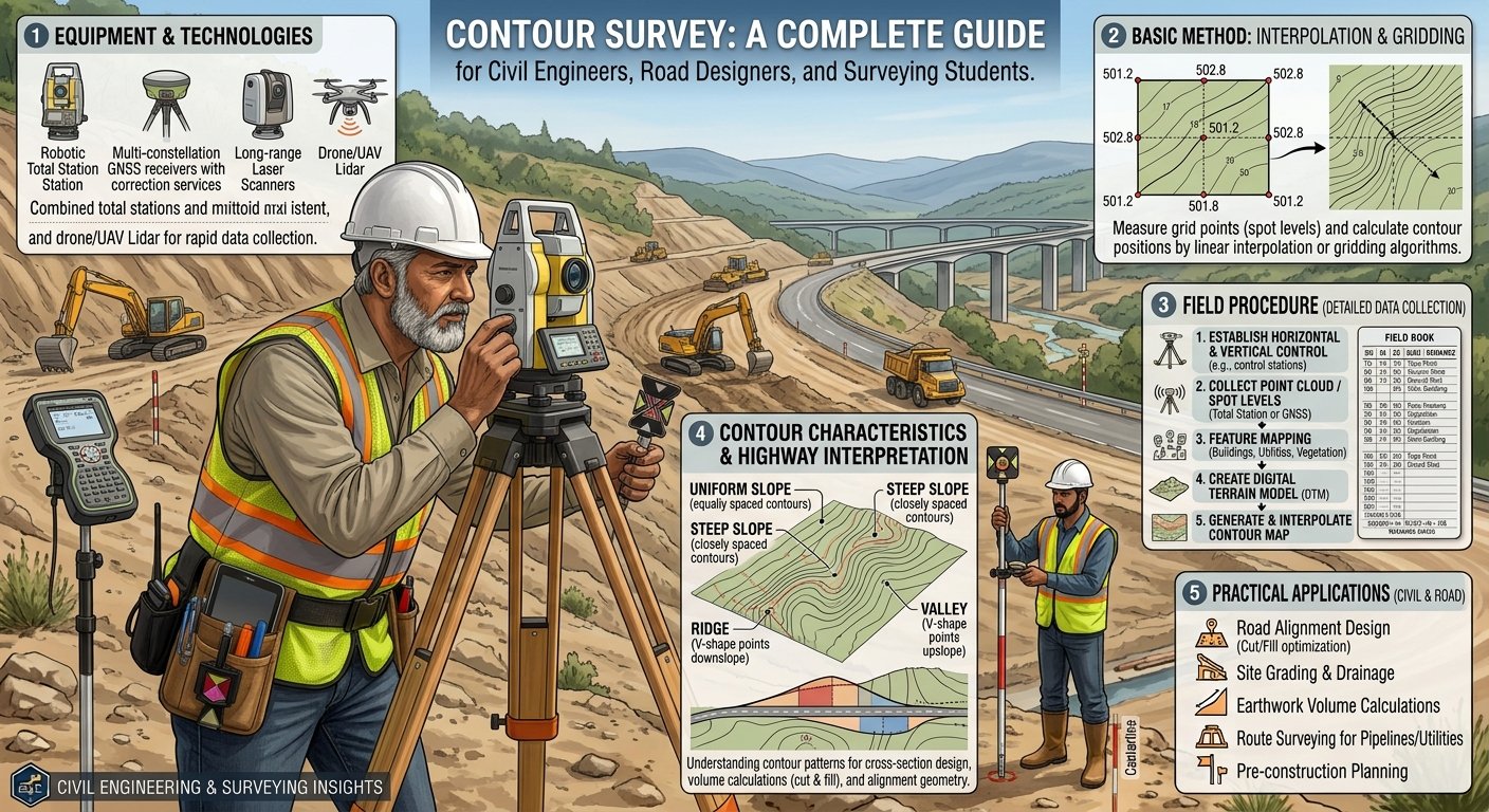
Introduction
Every successful road, highway, railway, canal, or building project begins with a clear understanding of the land. Engineers cannot design safe and economical infrastructure without knowing the shape, slope, and elevation of the terrain. This is where a Contour Survey becomes an essential part of the surveying process.
A contour survey represents the ground surface by connecting points of equal elevation with contour lines. These lines reveal hills, valleys, ridges, depressions, and natural drainage patterns, allowing engineers to visualize the terrain before construction begins. Accurate contour data supports route selection, earthwork estimation, drainage planning, and geometric design while reducing construction costs and project risks.
Whether you are a civil engineering student learning surveying fundamentals, a contractor planning site development, or a highway engineer selecting the best road alignment, understanding Contour Survey helps you make informed engineering decisions. This guide explains contour surveys in simple language while covering engineering principles, practical applications, field methods, and industry best practices.
What is Contour Survey?
A Contour Survey is a topographic surveying method used to determine the elevation of different points on the ground and represent them with contour lines on a map. Each contour line joins points having the same reduced level (RL), making it easier to understand the shape and slope of the land.
Unlike a simple level survey that measures individual elevations, a contour survey provides a complete picture of the terrain. Engineers use this information to identify high and low areas, estimate earthwork quantities, design drainage systems, and select the most suitable alignment for roads and highways.
Definition
Contour Survey is the process of locating points with equal elevations and plotting them on a plan to represent the natural configuration of the ground surface.
Objectives of Contour Survey
A contour survey serves several engineering purposes beyond measuring ground levels.
Main Objectives
- Determine the topography of a site.
- Identify hills, valleys, ridges, and depressions.
- Assist in highway and railway alignment.
- Estimate cutting and filling quantities.
- Plan drainage systems.
- Support site grading and land development.
- Select suitable locations for bridges, culverts, and retaining walls.
- Prepare contour maps for engineering design.
Importance of Contour Survey in Civil Engineering
Modern infrastructure projects rely heavily on contour surveys because terrain directly affects construction costs, safety, and long-term performance.
1. Highway Planning
Road engineers use contour maps to select economical routes with gentle gradients, reducing excavation, embankment work, and fuel consumption for vehicles.
2. Earthwork Estimation
Contour data allows engineers to calculate the volume of cut and fill accurately, improving project budgeting and construction planning.
3. Drainage Design
Water naturally flows from higher elevations to lower elevations. Contour surveys help engineers design effective side drains, culverts, stormwater channels, and cross-drainage structures.
4. Site Development
Builders use contour information to plan building platforms, access roads, parking areas, and utility layouts while minimizing unnecessary earthwork.
5. Environmental Planning
Contour maps help preserve natural drainage paths, reduce erosion, and minimize environmental impacts during construction.
Basic Terminology
Understanding contour surveying requires familiarity with several key terms.
Contour Line
A contour line connects points with the same elevation above a reference level, usually mean sea level.
Example
If every point on a line has an elevation of 150 m, that entire line represents the 150 m contour.
Contour Interval
The contour interval is the vertical distance between two adjacent contour lines.
Example
If contour lines appear at:
- 100 m
- 102 m
- 104 m
- 106 m
the contour interval equals 2 m.
A smaller contour interval provides greater detail, while a larger interval suits large-scale surveys.
Horizontal Equivalent
Horizontal equivalent refers to the horizontal distance between two consecutive contour lines.
The spacing changes according to ground slope:
- Close spacing indicates a steep slope.
- Wide spacing indicates a gentle slope.
Bench Mark (BM)
A Bench Mark is a permanent reference point with a known elevation. Surveyors use it as the starting point for levelling and contour surveys.
Reduced Level (RL)
Reduced Level represents the elevation of a point relative to a chosen datum, typically mean sea level.
Accurate RL values form the foundation of every contour map.
Engineering Principles of Contour Survey
Contour surveys follow several important engineering principles.
Equal Elevation
Every point on a contour line has the same elevation.
Contours Never Cross
Two contour lines cannot intersect because one location cannot have two different elevations simultaneously.
Closed Curves
Contour lines always form closed loops, either within or outside the map boundaries.
Perpendicular to Slope
Contours intersect the direction of maximum slope at approximately right angles.
Spacing Indicates Terrain
- Closely spaced contours indicate steep terrain.
- Widely spaced contours indicate gentle terrain.
- Uniform spacing indicates a consistent slope.
Understanding these principles allows engineers to interpret contour maps accurately.
Types of Contour Survey
Surveyors select different contour survey approaches depending on project size, terrain, and accuracy requirements.
Detailed Contour Survey
Engineers use this method for:
- Highway projects
- Building construction
- Airport development
- Dam construction
- Industrial sites
This survey provides highly accurate elevation data.
Reconnaissance Contour Survey
This preliminary survey gathers general topographic information during the planning stage.
It supports:
- Route selection
- Feasibility studies
- Site comparison
- Initial project planning
Although less detailed, it helps engineers identify suitable project locations quickly.
Methods of Contour Survey
Surveyors generally adopt two methods to obtain contour data.
Direct Method
In the direct method, surveyors locate points that already have the required elevation.
Procedure
- Set up the leveling instrument.
- Identify points with the desired reduced level.
- Mark each point in the field.
- Connect points of equal elevation on the map.
Advantages
- High accuracy.
- Reliable contour maps.
- Suitable for detailed engineering works.
Limitations
- Time-consuming.
- Labor-intensive.
- Less suitable for large areas.
Indirect Method
The indirect method records spot levels at selected locations instead of locating contour points directly.
Engineers later interpolate contour lines between measured points.
Common Techniques
- Grid Method
- Cross-Section Method
- Radial Line Method
- Tacheometric Method
Advantages
- Faster fieldwork.
- Economical for large projects.
- Easier data collection.
Limitations
- Accuracy depends on interpolation.
- Requires careful plotting.
Equipment Used in Contour Survey
Modern contour surveys combine traditional surveying instruments with advanced digital technologies.
Common Equipment
- Automatic Level
- Dumpy Level
- Digital Level
- Total Station
- GPS/GNSS Receiver
- Theodolite
- Levelling Staff
- Tripod Stand
- Measuring Tape
- Ranging Rods
- Pegs
- Survey Field Book
- Data Collector
- Drone (UAV) with Photogrammetry Software
- GIS and CAD Software for contour mapping
The choice of equipment depends on project accuracy, terrain, budget, and available technology.
Contour Survey Workflow Diagram
Project Planning
       │
       ▼
Reconnaissance Survey
       │
       ▼
Establish Bench Mark (BM)
       │
       ▼
Field Levelling
       │
       ▼
Collect Spot Levels
       │
       ▼
Plot Reduced Levels (RL)
       │
       ▼
Draw Contour Lines
       │
       ▼
Prepare Final Contour Map
Reading a Contour Map Diagram
             Hill

           180 m
         ┌────────┐
        170 m     │
      ┌──────────────┐
     160 m           │
   ┌────────────────────┐
 150 m                  │
────────────────────────────

Close contour spacing = Steep Slope

Wide contour spacing = Gentle Slope
Step-by-Step Contour Survey Procedure
A systematic approach ensures accurate contour maps and reliable engineering data. Each stage builds on the previous one, so survey teams must complete every task with precision.
Step 1: Study the Project Requirements
Engineers begin by reviewing the project scope, site boundaries, design objectives, and required survey accuracy. They also identify existing maps, satellite imagery, and previous survey records.
Step 2: Conduct a Reconnaissance Survey
The survey team visits the site to understand the terrain and identify obstacles such as buildings, rivers, dense vegetation, or steep slopes. This visit also helps determine the most suitable survey method and equipment.
Step 3: Establish Bench Marks (BM)
Surveyors establish permanent or temporary Bench Marks at stable locations. These reference points provide known elevations that serve as the starting point for all level measurements.
Step 4: Set Up Survey Equipment
The team installs and levels instruments such as an Automatic Level, Digital Level, or Total Station. Proper instrument setup ensures accurate observations throughout the survey.
Step 5: Collect Elevation Data
Surveyors measure spot levels across the site using the selected survey method. They record every observation carefully in a field book or digital data collector.
Step 6: Calculate Reduced Levels (RL)
Engineers calculate the Reduced Level for each surveyed point using standard leveling procedures. Accurate calculations prevent errors during contour plotting.
Step 7: Plot Survey Points
The collected coordinates and elevations are transferred to CAD or GIS software. Engineers plot every point according to its location and elevation.
Step 8: Draw Contour Lines
Points with equal elevations are connected smoothly to create contour lines. Engineers maintain consistent contour intervals throughout the map.
Step 9: Verify the Contour Map
The final drawing undergoes quality checks to confirm accuracy, continuity, and consistency. Any doubtful observations are verified through additional field measurements.
Practical Applications of Contour Survey in Road Engineering
Contour surveys support almost every stage of highway planning and design. Accurate topographic information allows engineers to optimize road alignments, minimize earthwork, and improve safety.
1. Highway Route Selection
Engineers compare multiple alignments using contour maps to identify the most economical route. Gentle slopes often reduce excavation costs and improve driving conditions.
Example
A contour map may reveal that one alignment crosses a steep hill while another follows a natural valley. Selecting the valley route can significantly reduce cutting, filling, and construction expenses.
2. Geometric Road Design
Road designers use contour information to establish:
- Longitudinal gradients
- Vertical curves
- Horizontal curves
- Sight distances
- Formation levels
Proper geometric design improves vehicle safety and ride quality.
3. Earthwork Estimation
Contour maps help engineers calculate:
- Excavation volume
- Embankment volume
- Cut-and-fill balance
Accurate estimates improve project budgeting and construction scheduling.
4. Drainage Planning
Surface water naturally follows the terrain. Contour maps enable engineers to design efficient drainage systems, including:
- Side drains
- Culverts
- Stormwater channels
- Cross-drainage structures
Effective drainage protects the pavement structure and reduces maintenance costs.
5. Bridge and Culvert Location
Engineers use contour data to identify suitable crossing points for rivers, streams, and drainage channels. This information helps optimize bridge length and foundation design.
6. Land Development
Contour surveys also support:
- Residential developments
- Industrial parks
- Airports
- Dams
- Reservoirs
- Railway projects
- Canal construction
Engineering Best Practices for Contour Survey
Experienced surveyors follow several best practices to improve data quality and project efficiency.
- Establish stable Bench Marks before starting fieldwork.
- Calibrate survey instruments regularly.
- Select contour intervals appropriate for the terrain.
- Double-check field observations.
- Use GPS or Total Station for higher accuracy on large projects.
- Record weather conditions during surveying.
- Maintain organized field notes.
- Verify doubtful measurements immediately.
- Use CAD or GIS software for contour generation.
- Conduct independent quality checks before issuing final maps.
These practices improve reliability and reduce costly design errors.
Common Mistakes to Avoid
Even small surveying errors can affect an entire engineering project.
Frequent Mistakes
- Using uncalibrated equipment.
- Selecting inappropriate contour intervals.
- Poor instrument leveling.
- Incorrect Reduced Level calculations.
- Inadequate field notes.
- Skipping quality checks.
- Ignoring terrain features during interpolation.
- Failing to verify Bench Marks.
- Relying solely on estimated elevations.
- Neglecting equipment maintenance.
Avoiding these mistakes improves survey accuracy and project outcomes.
Practical Recommendations
Civil Engineers
- Review contour maps before beginning geometric design.
- Coordinate with geotechnical engineers during alignment selection.
- Validate digital survey data with field observations.
- Consider future expansion during highway planning.
Contractors
- Verify site levels before starting earthwork.
- Protect established Bench Marks throughout construction.
- Update contour information after major excavation or filling activities.
- Train survey teams on modern equipment and software.
Engineering Students
- Practice contour plotting manually before using software.
- Learn the relationship between contour spacing and ground slope.
- Participate in field surveys to gain practical experience.
- Develop proficiency in Total Station, GPS, CAD, and GIS applications.
General Discussion on IRC, AASHTO, and ICE Practices
Professional engineering organizations emphasize the importance of accurate topographic surveys during infrastructure planning.
IRC (Indian Roads Congress)
IRC recommends detailed topographic surveys during highway planning to support route selection, geometric design, earthwork estimation, and drainage planning.
AASHTO
AASHTO highlights the need for reliable terrain data when designing highways, ensuring safe alignments, proper sight distances, and efficient drainage systems.
ICE (Institution of Civil Engineers)
ICE encourages the use of modern surveying technologies, quality assurance procedures, and professional competence to deliver accurate engineering surveys.
Although project requirements vary across countries, these organizations share common principles:
- Accurate field measurements
- Proper documentation
- Quality control
- Suitable survey methods
- Reliable data processing
- Continuous professional development
Advantages of Contour Survey
- Provides a clear representation of terrain.
- Supports accurate engineering design.
- Improves highway alignment selection.
- Reduces construction costs.
- Assists in earthwork estimation.
- Enhances drainage planning.
- Supports environmental assessment.
- Increases project efficiency.
- Improves decision-making.
- Reduces design revisions.
Frequently Asked Questions (FAQs)
1. What is a contour survey?
A contour survey is a topographic survey that identifies points of equal elevation and connects them with contour lines to represent the shape of the ground.
2. Why is a contour survey important in road construction?
It helps engineers select economical alignments, estimate earthwork quantities, design drainage systems, and improve roadway safety.
3. Which instruments are commonly used for contour surveys?
Common instruments include Automatic Levels, Digital Levels, Total Stations, GPS/GNSS receivers, drones, and leveling staffs.
4. What is a contour interval?
A contour interval is the vertical difference in elevation between two adjacent contour lines on a map.
5. What is the difference between direct and indirect contouring?
The direct method locates points of equal elevation in the field, while the indirect method measures spot levels and interpolates contour lines later.
6. How does contour spacing indicate ground slope?
Closely spaced contours represent steep slopes, while widely spaced contours indicate gentle slopes.
7. What industries use contour surveys?
Civil engineering, highway construction, railway engineering, mining, irrigation, urban planning, environmental engineering, and land development all rely on contour surveys.
8. How do drones improve contour surveys?
Drones equipped with cameras or LiDAR sensors collect high-resolution topographic data quickly, reducing field time while improving coverage and accuracy.
9. Can contour surveys reduce construction costs?
Yes. Accurate contour information helps optimize alignments, minimize unnecessary excavation, improve drainage design, and reduce design changes during construction.
10. Which software is commonly used for contour mapping?
Engineers frequently use AutoCAD Civil 3D, Bentley OpenRoads, ArcGIS, QGIS, and other surveying software to generate contour maps and terrain models.
Conclusion
A Contour Survey forms the foundation of successful civil engineering and road infrastructure projects by providing an accurate representation of the natural terrain. Engineers use contour maps to understand elevation changes, select suitable highway alignments, estimate earthwork quantities, design efficient drainage systems, and improve construction planning. Careful field measurements, proper equipment selection, and systematic data processing ensure reliable survey results that support safe and economical designs. Modern technologies such as Total Stations, GPS/GNSS receivers, drones, and GIS software have significantly improved the speed and accuracy of contour mapping, yet sound surveying principles remain essential. Whether planning a highway, railway, dam, airport, or urban development, a well-executed Contour Survey reduces project risks, controls costs, and enhances long-term infrastructure performance. Civil engineers, contractors, and surveying students who master contour surveying techniques gain a valuable skill that strengthens decision-making and contributes to the successful delivery of sustainable engineering projects.

Kamran Malik is a passionate civil engineering writer and researcher who specializes in construction, transportation, structural engineering, and infrastructure topics. Through his articles on CivilEngineerings.com, he simplifies complex engineering concepts and shares practical insights, industry trends, and educational resources for students, professionals, and engineering enthusiasts.