
Introduction
Modern transportation projects demand speed, precision, and compliance with engineering standards. Civil 3D Road Design has become one of the most powerful solutions for designing highways, urban roads, rural roads, and transportation corridors with greater efficiency and accuracy. Unlike traditional drafting methods, Autodesk Civil 3D integrates terrain modeling, alignments, profiles, corridors, grading, and quantity calculations into a single intelligent environment.
Whether you’re a civil engineering student, highway engineer, consultant, contractor, or researcher, understanding Civil 3D can significantly improve your road design workflow. This comprehensive guide explains the complete road design process, essential engineering principles, practical calculations, quality control methods, industry standards, and professional best practices to help you develop reliable and construction-ready highway projects.
What is Civil 3D Road Design?
Civil 3D Road Design is the process of planning, modeling, analyzing, and documenting roads using Autodesk Civil 3D software. It combines geometric road design with digital terrain modeling, enabling engineers to produce highly accurate highway layouts while minimizing design errors.
The software supports:
- Highway design
- Rural road projects
- Urban streets
- Expressways
- Interchanges
- Industrial roads
- Airport access roads
- Service roads
Civil 3D creates intelligent models where any design change automatically updates related drawings, profiles, cross sections, and quantities.
Why Civil 3D is Used in Highway Engineering
Civil 3D has transformed transportation engineering by replacing manual drafting with intelligent design automation.
Major advantages include:
- Faster project development
- Accurate terrain modeling
- Automatic cross-section generation
- Dynamic corridor modeling
- Easy quantity estimation
- Better BIM integration
- Reduced design errors
- Improved collaboration among engineers
It significantly reduces redesign time when project revisions occur.
Main Components of Civil 3D Road Design
Horizontal Alignment Design
Horizontal alignment defines the road centerline.
It includes:
- Tangents
- Circular curves
- Spiral transitions
- Intersection geometry
Typical design considerations:
- Design speed
- Sight distance
- Radius
- Superelevation
- Safety
Vertical Profile Design
Profiles define roadway elevations.
Key elements include:
- Existing Ground (EG)
- Finished Ground (FG)
- Vertical curves
- Grades
- Crest curves
- Sag curves
Proper profile design ensures:
- Safe driving
- Effective drainage
- Comfortable riding quality
Assembly Creation
Assemblies represent the road template.
Typical components:
- Lane
- Shoulder
- Median
- Side slope
- Curb
- Sidewalk
- Ditch
Civil 3D allows multiple assemblies for varying road conditions.
Corridor Modeling
The corridor is the heart of Civil 3D Road Design.
It combines:
- Alignment
- Profile
- Assembly
The software automatically creates:
- Finished surfaces
- Daylight lines
- Cut/fill slopes
- Corridor surfaces
Surface Creation
Surfaces represent existing and proposed terrain.
Surface types:
- Existing Ground Surface
- Finished Surface
- Corridor Surface
- Volume Surface
These are generated using survey points, contours, breaklines, or point clouds.
Cross Sections
Civil 3D automatically generates:
- Existing sections
- Finished sections
- Earthwork sections
- Quantity reports
Cross sections help contractors understand construction requirements.
Earthwork Calculation
Earthwork estimation is one of Civil 3D’s strongest features.
It calculates:
- Cut volume
- Fill volume
- Net balance
- Borrow quantity
- Waste quantity
Accurate earthwork estimates reduce project costs.
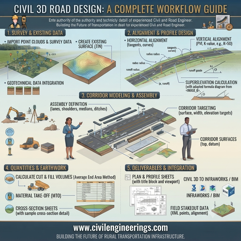
Step-by-Step Civil 3D Road Design Process
Step 1: Import Survey Data
Input:
- GPS survey
- Total Station data
- Drone survey
- LiDAR
↓
Step 2: Create Existing Surface
Generate a digital terrain model (DTM).
↓
Step 3: Design Horizontal Alignment
Establish the road centerline.
↓
Step 4: Create Vertical Profile
Develop the proposed road elevations.
↓
Step 5: Build Assemblies
Define pavement layers and road components.
↓
Step 6: Create Corridor
Generate the 3D roadway model.
↓
Step 7: Generate Cross Sections
Review geometry and earthwork.
↓
Step 8: Quantity Estimation
Calculate:
- Earthwork
- Pavement materials
- Shoulder quantities
↓
Step 9: Final Drawings
Produce:
- Plan
- Profile
- Cross sections
- Quantity tables
Road Design Workflow Diagram
Survey Data
     │
     ▼
Existing Surface
     │
     ▼
Horizontal Alignment
     │
     ▼
Vertical Profile
     │
     ▼
Assembly
     │
     ▼
Corridor Model
     │
     ▼
Cross Sections
     │
     ▼
Earthwork
     │
     ▼
Construction Drawings
Engineering Calculations
Although Civil 3D automates calculations, engineers should understand the underlying principles.
1. Road Gradient
Formula
Gradient (%) = (Vertical Rise / Horizontal Distance) × 100
Example:
Rise = 3 m
Distance = 150 m
Gradient = (3 ÷ 150) ×100
= 2%
2. Superelevation
General relationship:
e + f = V² / (127R)
Where:
- e = Superelevation
- f = Side friction
- V = Speed (km/h)
- R = Radius (m)
Example:
Speed = 80 km/h
Radius = 300 m
The calculated value helps determine the required superelevation for safe vehicle movement.
3. Earthwork Volume
Volume
= Average Area × Length
Example:
Area₁ = 40 m²
Area₂ = 60 m²
Distance = 20 m
Average Area
= (40+60)/2
=50 m²
Volume
=50×20
= 1000 m³
Engineering Assumptions
Typical assumptions include:
- Stable soil conditions
- Accurate survey data
- Proper drainage
- Standard pavement materials
- Appropriate traffic loading
- Reliable design speed
These assumptions should always be validated during detailed project design.
Quality Control Tests
High-quality construction depends on proper field and laboratory testing.
CBR Test
Determines the bearing capacity of subgrade soil for pavement design.
Proctor Test
Measures the optimum moisture content and maximum dry density to achieve proper compaction.
Marshall Stability Test
Evaluates asphalt mix stability, flow, and durability.
Slump Test
Checks the workability and consistency of fresh concrete used in culverts, retaining walls, and bridges.
Core Test
Verifies asphalt pavement thickness and in-place density after construction.
Density Test
Confirms field compaction using sand cone or nuclear density methods.
Plate Load Test
Measures the load-bearing capacity and settlement characteristics of pavement foundations and subgrades.
Best Practices for
Engineers
- Use verified survey data before modeling.
- Review corridor targets carefully.
- Perform regular design checks.
- Validate earthwork quantities.
- Coordinate with drainage and utility teams.
- Maintain organized Civil 3D templates.
Contractors
- Compare drawings with site conditions.
- Follow approved alignment coordinates.
- Monitor compaction during every layer.
- Verify elevations before paving.
- Conduct quality testing regularly.
Students
- Practice creating complete road models.
- Understand geometric design principles before using software.
- Learn surface modeling thoroughly.
- Study real highway projects.
- Develop skills in quantity estimation and corridor editing.
Common Mistakes
Many beginners make avoidable errors that can affect project quality.
Common mistakes include:
- Using poor-quality survey data.
- Ignoring existing utilities.
- Incorrect assembly configuration.
- Poor corridor targeting.
- Not checking design criteria.
- Overlooking drainage requirements.
- Inaccurate earthwork balancing.
- Skipping quality assurance reviews.
- Excessive corridor regions.
- Failure to update surfaces after revisions.
Avoiding these issues results in smoother workflows and more reliable construction documents.
General Overview of Engineering Standards
Professional road projects developed in Civil 3D should align with recognized engineering guidance from leading organizations. In many countries, designers refer to the Indian Roads Congress (IRC) for highway planning and geometric design concepts, while the American Association of State Highway and Transportation Officials (AASHTO) provides widely respected guidance on roadway geometry and transportation engineering. Material testing procedures are commonly based on ASTM standards, and the Federal Highway Administration (FHWA) publishes best practices for highway planning and safety. International quality management principles are often supported by ISO, and engineering professionals may also consult guidance from the Institution of Civil Engineers (ICE). Engineers should always follow the latest standards and project-specific specifications applicable in their region.
Frequently Asked Questions
1. Is Civil 3D suitable for complete highway design?
Yes. Civil 3D supports the complete highway design process, including terrain modeling, alignments, profiles, corridors, grading, cross sections, and quantity estimation. It also simplifies revisions by automatically updating related design elements, making it ideal for both small road improvements and large transportation infrastructure projects.
2. What skills should beginners learn before using Civil 3D?
Students should first understand surveying, road geometry, coordinate systems, and basic highway engineering. Learning horizontal and vertical alignment principles, cross sections, and earthwork concepts makes Civil 3D much easier to use. Practical projects help reinforce software skills alongside engineering knowledge.
3. How does Civil 3D improve project accuracy?
Civil 3D uses intelligent objects that remain connected throughout the design process. If an alignment or profile changes, related corridors, surfaces, and sections update automatically. This dynamic workflow reduces drafting errors, improves consistency, and minimizes rework during project development.
4. Can Civil 3D calculate earthwork quantities automatically?
Yes. The software generates cut-and-fill volumes by comparing existing and proposed surfaces. Engineers can review quantity reports, balance earthworks, and optimize grading plans, helping reduce material waste, transportation costs, and overall construction expenses.
5. Why are quality control tests important in road projects?
Quality control tests ensure that construction materials and workmanship meet design requirements. Tests such as CBR, Proctor, Marshall Stability, Slump, Core, Density, and Plate Load verify soil strength, compaction, asphalt performance, and concrete quality. Regular testing reduces the risk of premature pavement failure.
6. Which industries use Civil 3D Road Design?
Civil 3D is widely used by highway authorities, engineering consultants, contractors, infrastructure developers, municipalities, transportation agencies, mining companies, and airport planners. Its versatility makes it suitable for projects ranging from local roads to major expressways and industrial access routes.
Conclusion
Civil 3D Road Design has revolutionized modern highway engineering by combining intelligent modeling, automation, and precise engineering workflows into a single platform. From survey data processing and alignment creation to corridor modeling, cross sections, and earthwork calculations, the software helps engineers deliver accurate, efficient, and construction-ready road designs. When paired with sound engineering judgment, quality control testing, and adherence to recognized standards, Civil 3D becomes an invaluable tool for designing safe and sustainable transportation infrastructure. Whether you are a student building foundational skills or a professional managing complex highway projects, mastering Civil 3D Road Design will enhance productivity and improve project outcomes. Start applying these principles in real-world projects to develop smarter, safer, and more efficient road networks.
