
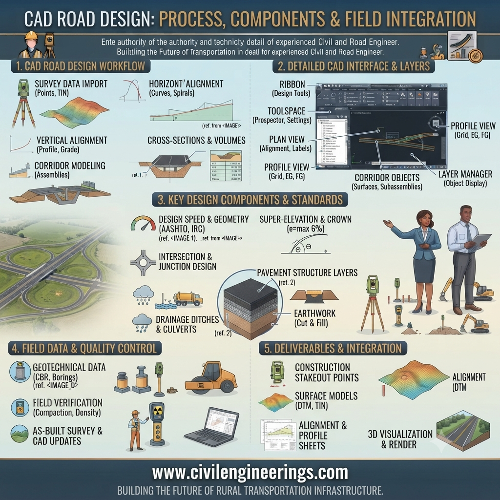
Introduction
Modern highways demand precision, efficiency, and long-term performance. Traditional drafting methods have largely been replaced by digital workflows that improve accuracy and reduce costly construction errors. CAD Road Design has become an essential part of transportation engineering, enabling engineers to create detailed alignments, profiles, cross-sections, and construction drawings with remarkable speed and consistency.
Whether you’re a civil engineering student learning highway design, a consultant preparing infrastructure projects, or a contractor reviewing construction plans, understanding CAD-based road design is a valuable professional skill. This guide explains the complete workflow, engineering principles, calculations, quality control procedures, industry standards, and best practices that help transform a conceptual road into a safe, durable, and efficient transportation facility.
What is CAD Road Design?
CAD Road Design refers to the use of Computer-Aided Design (CAD) software to plan, model, analyze, and document road and highway infrastructure. Instead of producing drawings manually, engineers create intelligent digital models containing geometry, elevations, drainage systems, pavement layers, earthwork quantities, and utility information.
Modern CAD platforms commonly support:
- Horizontal alignment design
- Vertical profile design
- Corridor modeling
- Cross-section generation
- Earthwork calculations
- Drainage layouts
- Quantity estimation
- Construction documentation
- 3D visualization
- BIM integration
The result is greater design accuracy, improved collaboration, and reduced construction risks.
Why CAD Road Design Matters
Transportation projects involve thousands of engineering decisions. CAD software helps organize these decisions into an integrated digital environment.
Major benefits include:
- Improved geometric accuracy
- Faster revisions
- Reduced drafting errors
- Better visualization
- Easier quantity estimation
- Efficient collaboration
- Lower project costs
- Enhanced construction coordination
- Better documentation
- Simplified maintenance planning
Main Components of CAD Road Design
1. Survey Data
Every successful design starts with accurate topographic information.
Survey inputs include:
- Ground elevations
- Existing roads
- Utilities
- Rivers
- Buildings
- Property boundaries
- Benchmarks
- Control points
Accurate survey data reduces redesign during construction.
2. Horizontal Alignment
The horizontal alignment determines the road’s path.
Elements include:
- Tangents
- Circular curves
- Transition curves
- Spiral curves
- Curve widening
- Superelevation transitions
Objectives include:
- Safety
- Driver comfort
- Land optimization
- Minimum earthwork
3. Vertical Alignment
Vertical alignment controls road elevations.
Components include:
- Gradients
- Crest curves
- Sag curves
- Vertical intersections
- Drainage slopes
Proper vertical design improves visibility and minimizes construction costs.
4. Typical Cross Section
Typical sections define the structural and geometric layout.
Example:
 Shoulder   Lane     Median     Lane    Shoulder
-------------------------------------------------
|        |        |        |        |
|        |        |        |        |
-------------------------------------------------
Subgrade
Typical components:
- Lanes
- Median
- Shoulder
- Side slopes
- Drainage ditch
- Pavement layers
5. Corridor Modeling
Corridor modeling combines:
- Horizontal alignment
- Vertical profile
- Typical section
This creates a complete 3D road model that automatically updates when design changes occur.
Complete CAD Road Design Workflow
Step 1: Import Survey Data
Engineers import:
- Total Station data
- GPS surveys
- Drone mapping
- LiDAR
- GIS information
Step 2: Build Existing Terrain
Software generates:
- Digital Terrain Model (DTM)
- Surface contours
- Existing ground profile
Step 3: Design Horizontal Alignment
Engineers establish:
- Design speed
- Curve radius
- Transition lengths
- Lane widths
Step 4: Create Vertical Profile
Profile design includes:
- Finished road levels
- Cut and fill balancing
- Vertical curves
- Drainage considerations
Step 5: Build Assembly
Assemblies define:
- Pavement layers
- Shoulders
- Curbs
- Side slopes
- Ditches
Step 6: Generate Corridor
The corridor automatically creates:
- Cross sections
- Earthwork
- Surface model
- Material quantities
Step 7: Quantity Estimation
CAD software calculates:
- Excavation
- Embankment
- Asphalt volume
- Concrete quantity
- Aggregate volume
- Drainage structures
Step 8: Construction Drawings
Typical drawings include:
- Plan view
- Profile view
- Cross sections
- Pavement details
- Drainage plans
- Road markings
Essential Engineering Calculations
Earthwork Volume
Formula:
[
Volume=\frac{A_1+A_2}{2}\times L
]
Where:
- A₁ = First cross-sectional area (m²)
- A₂ = Second cross-sectional area (m²)
- L = Distance (m)
Example
A₁ = 18 m²
A₂ = 26 m²
Distance = 20 m
Volume
= (18+26)/2 ×20
=22×20
= 440 m³
Road Gradient
Formula
Gradient (%)
= Rise / Run ×100
Example
Rise = 4 m
Run = 120 m
Gradient
=4/120×100
= 3.33%
Superelevation
Formula
[
e+f=\frac{V^2}{127R}
]
Where
e = Superelevation
f = Side friction
V = Speed (km/h)
R = Radius (m)
This equation assists in selecting safe curve geometry.
ASCII Road Design Diagrams
Road Cross Section
 Shoulder   Lane      Lane    Shoulder
    \         |         |         /
     \        |         |        /
-----------------------------------------
 Asphalt Surface
-----------------------------------------
 Base Course
-----------------------------------------
 Subbase
-----------------------------------------
 Compacted Subgrade
Road Profile
Elevation

      Crest
        /\
       /  \
______/    \_________

Chainage →
Horizontal Alignment
--------\
         \
          )
         /
--------/
Quality Control and Testing
Good CAD models must be supported by quality field data and verified materials.
CBR Test
Determines subgrade strength for pavement design.
Proctor Test
Determines:
- Maximum Dry Density
- Optimum Moisture Content
Essential for field compaction.
Marshall Stability Test
Used for asphalt mixtures to evaluate:
- Stability
- Flow
- Mix performance
Slump Test
Measures concrete workability before placement.
Density Test
Verifies field compaction of:
- Subgrade
- Subbase
- Base course
Core Test
Determines:
- Asphalt thickness
- Density
- Material quality
Plate Load Test
Evaluates the bearing capacity and stiffness of the foundation supporting the pavement structure.
Industry Standards (General Overview)
Successful CAD Road Design should align with recognized engineering guidance from leading organizations.
IRC
Provides comprehensive guidance for highway geometry, pavement design, drainage, and road safety suited to varying traffic conditions.
AASHTO
Offers internationally respected recommendations for geometric design, pavement engineering, bridge coordination, and transportation planning.
ASTM
Develops standardized laboratory and field testing methods for soils, aggregates, asphalt, and concrete materials.
ICE
Promotes engineering best practices, professional competence, and sustainable infrastructure development.
ISO
Supports quality management, environmental systems, and information management processes across engineering projects.
FHWA
Publishes technical resources on roadway design, safety improvements, asset management, and transportation innovation.
Best Practices for
Engineers
- Validate survey data before modeling.
- Use consistent coordinate systems.
- Check alignment continuity.
- Review earthwork balance.
- Verify drainage paths.
- Perform independent design checks.
- Maintain organized CAD layers and naming conventions.
Contractors
- Compare drawings with site conditions.
- Verify benchmarks before construction.
- Follow approved material specifications.
- Monitor compaction regularly.
- Record field changes accurately.
- Coordinate with survey teams to minimize rework.
Students
- Learn roadway geometry fundamentals before using CAD software.
- Practice with real survey datasets.
- Understand corridor modeling concepts.
- Study pavement design principles.
- Build proficiency in quantity estimation and drafting standards.
Common Mistakes
- Using inaccurate survey information.
- Ignoring drainage requirements.
- Designing unsafe curve radii.
- Inconsistent cross sections.
- Poor layer management in CAD files.
- Overlooking utility conflicts.
- Incorrect earthwork calculations.
- Failing to check design standards.
- Neglecting quality control during construction.
- Inadequate documentation for revisions and approvals.
Frequently Asked Questions
1. What is CAD Road Design used for?
CAD Road Design is used to create accurate digital models of roads, highways, and streets. Engineers use it to develop horizontal and vertical alignments, cross-sections, drainage layouts, and construction drawings. It also assists with earthwork estimation, material quantities, and design revisions. By integrating survey data with intelligent modeling tools, CAD improves project accuracy, reduces drafting time, and supports better decision-making throughout planning, construction, and maintenance.
2. Which professionals benefit most from CAD Road Design?
Civil engineers, highway engineers, transportation planners, consultants, contractors, surveyors, and infrastructure researchers all benefit from CAD Road Design. Students also gain practical skills by learning digital design workflows. Because modern road projects rely heavily on computer-based modeling, proficiency in CAD software enhances collaboration, improves documentation quality, and increases efficiency across multidisciplinary engineering teams.
3. Why is survey accuracy important in CAD Road Design?
Accurate survey data forms the foundation of every road model. Errors in elevations, coordinates, or existing features can lead to incorrect alignments, inaccurate earthwork quantities, drainage problems, and costly redesign during construction. Engineers should verify benchmarks, validate coordinate systems, and review terrain models before beginning detailed design to ensure reliable project outcomes.
4. How does CAD software improve highway design?
CAD software streamlines highway design by automating repetitive tasks, generating intelligent 3D models, updating drawings after revisions, and calculating earthwork quantities. It also enhances visualization, facilitates clash detection, and supports better communication among designers, contractors, and clients. These capabilities reduce design time while improving consistency and construction readiness.
5. What quality control tests are commonly associated with road projects?
Typical quality control tests include the California Bearing Ratio (CBR) test for subgrade strength, Proctor test for compaction characteristics, Marshall Stability test for asphalt performance, Slump test for concrete workability, Density test for field compaction, Core test for asphalt verification, and Plate Load test for evaluating foundation support. Together, these tests help ensure the road performs as intended over its service life.
6. Can CAD Road Design reduce construction costs?
Yes. Accurate digital modeling minimizes design errors, optimizes earthwork, improves material estimation, and identifies conflicts before construction begins. These improvements reduce waste, avoid unnecessary rework, and help keep projects within budget. Early coordination through CAD also shortens project timelines and supports more efficient resource planning.
7. What software skills should aspiring highway engineers develop?
Aspiring highway engineers should build a strong understanding of CAD drafting, digital terrain modeling, corridor creation, geometric design, quantity estimation, and basic BIM concepts. Equally important are fundamentals in surveying, pavement engineering, drainage design, and transportation planning. Combining software proficiency with engineering knowledge leads to more effective and practical road design solutions.
Conclusion
CAD Road Design has transformed the way transportation infrastructure is planned, designed, and delivered. By integrating accurate survey data with intelligent digital modeling, engineers can produce safer alignments, optimize earthwork, streamline documentation, and improve collaboration throughout a project’s lifecycle. Successful road design, however, depends on more than software—it requires sound engineering judgment, adherence to recognized standards, rigorous quality control, and a thorough understanding of pavement, drainage, and geometric design principles. Whether you are a student building foundational skills or a practicing engineer managing complex highway projects, mastering CAD Road Design will enhance efficiency and project quality. Continue learning, practice with real-world datasets, and apply proven engineering methods to deliver reliable, sustainable, and high-performing transportation infrastructure.
