
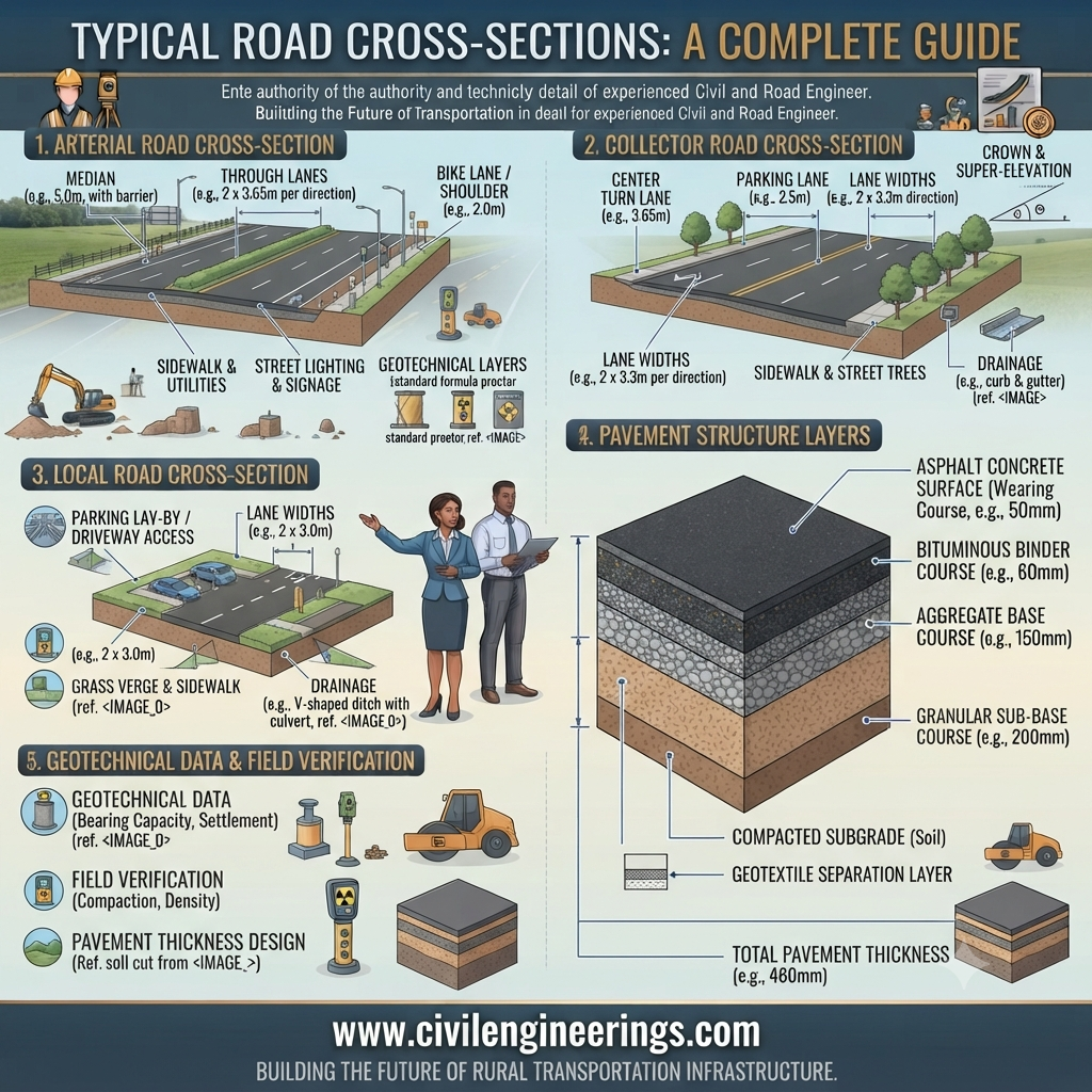
A road may look simple from the surface, but beneath that pavement lies a carefully engineered cross-sectional arrangement that determines its safety, strength, drainage, constructability, and long-term performance. Typical Cross Sections provide the standard geometric and structural framework that connects highway design calculations with actual field construction.
For a highway engineer, a typical cross section is more than a drawing. It is a practical engineering reference that defines how the carriageway, shoulders, median, pavement layers, side slopes, drainage facilities, right-of-way, and roadside elements should fit together. Contractors use these details to execute earthworks and pavement construction, while quantity surveyors rely on cross-sectional information for estimating excavation, embankment, and material requirements.
This guide explains Typical Cross Sections in highway engineering from both design and construction perspectives. It covers their definition, importance, major components, different roadway configurations, design factors, geometric considerations, cross-fall, side slopes, drainage, earthwork calculations, pavement layers, quality control, common mistakes, applicable standards, and practical recommendations for students, engineers, and contractors.
What Are Typical Cross Sections?
A typical cross section is a transverse representation of a roadway taken perpendicular to the centerline or direction of travel. It shows the arrangement, dimensions, slopes, elevations, and materials associated with the road corridor.
A typical highway cross section may identify:
- Carriageway width
- Number of traffic lanes
- Lane width
- Paved and unpaved shoulders
- Median
- Kerbs
- Footpaths
- Cycle tracks
- Camber or cross slope
- Pavement layers
- Side drains
- Embankment slopes
- Cut slopes
- Roadside safety features
- Utility corridors
- Right-of-way limits
The exact configuration depends on the road classification, traffic demand, design speed, terrain, climate, soil conditions, drainage requirements, and available right-of-way.
It is important to distinguish a typical cross section from a location-specific cross section. The typical section represents the standard arrangement intended for a particular roadway segment. Actual cross sections at individual chainages may change because of terrain, drainage structures, intersections, retaining walls, utilities, or other site conditions.
Why Are Typical Cross Sections Important?
A well-developed cross section creates consistency between highway design and construction. It also helps different project teams understand the intended roadway arrangement.
1. Improves Road Safety
Lane widths, shoulders, medians, clear zones, drainage features, and roadside slopes all influence road safety.
An inappropriate cross-sectional arrangement can create:
- Edge drop-offs
- Poor drainage
- Unsafe roadside conditions
- Insufficient recovery areas
- Conflicts between vehicles and pedestrians
2. Supports Pavement Performance
The pavement does not operate independently from the surrounding road structure.
The cross section determines how water moves away from the pavement and how loads interact with the pavement foundation. Proper shoulder support, subgrade preparation, drainage, and cross slope therefore contribute to pavement durability.
3. Improves Drainage
Water is one of the major causes of premature pavement deterioration.
An appropriate cross section provides a path for surface runoff through:
Pavement → Shoulder → Side Drain → Culvert/Outlet → Natural Drainage System
Without adequate cross slope and drainage, water can remain on the pavement or infiltrate pavement layers.
4. Helps Estimate Earthwork
Cross-sectional data provides the basis for calculating excavation and embankment quantities.
This information supports:
- Cost estimation
- Material planning
- Haulage planning
- Construction scheduling
- Contractor payment measurement
5. Provides Construction Control
The approved typical section gives site personnel a reference for checking:
- Formation width
- Pavement thickness
- Shoulder width
- Side slopes
- Drain dimensions
- Finished levels
Major Components of a Highway Cross Section
The components vary according to road type, but the following elements commonly appear in highway design.
1. Carriageway
The carriageway is the portion of the roadway provided for vehicle movement.
Its width depends on:
- Number of lanes
- Design vehicle
- Traffic volume
- Design speed
- Road classification
- Operating conditions
For example, a two-lane road may have a carriageway around 7.0–7.5 m wide, depending on the applicable national standard and project requirements.
Engineers should never select lane width solely from a generic value. The adopted width must come from the governing design standard and project-specific traffic analysis.
2. Traffic Lanes
Lane width influences vehicle operations, capacity, safety, and driver comfort.
Wider lanes can provide greater lateral clearance, while excessively wide lanes may encourage higher speeds in some urban environments.
Lane width should therefore be selected according to:
- Functional classification
- Design speed
- Traffic composition
- Heavy vehicle percentage
- Urban or rural setting
- Safety requirements
3. Shoulders
Shoulders are located adjacent to the carriageway.
They can be:
- Paved
- Gravel
- Earthen
- Partially paved
Shoulders serve several functions:
- Emergency stopping
- Lateral pavement support
- Vehicle recovery
- Maintenance access
- Pedestrian accommodation where appropriate
On high-speed roads, paved shoulders can provide an important recovery area and improve overall operational safety.
4. Median
A median separates opposing traffic flows on divided highways.
It may be:
- Raised
- Depressed
- Flush
- Landscaped
- Barrier-separated
Median design depends on available right-of-way, safety requirements, turning movements, drainage, maintenance, and future expansion.
A sufficiently designed median can reduce the likelihood of severe head-on collisions and provide space for traffic management infrastructure.
5. Camber or Cross Slope
Camber, also called cross fall or cross slope, is the transverse slope provided to remove water from the pavement surface.
The basic relationship is:
[
i = \frac{h}{L}\times100
]
Where:
- (i) = cross slope (%)
- (h) = vertical difference in elevation
- (L) = horizontal distance
Example
Suppose a pavement width is 7.0 m and the adopted cross slope is 2.5%.
[
h = 7.0 \times 0.025
]
[
h = 0.175,m
]
Thus, the elevation difference across the 7 m width is approximately 175 mm if the full width is measured from one edge to the opposite edge and the slope is applied uniformly in one direction.
However, many two-way roads crown at the center, so the actual edge-to-crown difference is calculated over half the carriageway width.
This distinction is important when preparing construction levels.
6. Pavement Layers
A complete highway cross section should show the pavement structure where appropriate.
A flexible pavement may contain:
- Wearing course
- Binder course
- Base course
- Subbase
- Compacted subgrade
A rigid pavement may consist of:
- Concrete slab
- Base or subbase
- Prepared subgrade
The actual layer thicknesses should come from the pavement design rather than from a generic typical section.
7. Kerbs
Kerbs are common in urban roads and built-up areas.
They help:
- Define pavement edges
- Control traffic
- Separate pedestrian areas
- Direct surface runoff
- Protect footpaths
Different kerb profiles are selected according to drainage and roadside requirements.
8. Footpaths and Cycle Facilities
Urban cross sections increasingly need to accommodate pedestrians and cyclists.
A modern cross section may include:
- Footpath
- Cycle track
- Planting strip
- Accessibility ramps
- Street furniture zone
- Bus stop area
Roadway design should consider all road users rather than focusing exclusively on motor vehicles.
9. Side Drain
Side drains collect runoff from the roadway and adjacent land.
Drain types may include:
- Open trapezoidal drains
- V-shaped drains
- Rectangular drains
- Lined drains
- Covered drains
Drain capacity should be checked against expected runoff rather than selecting dimensions arbitrarily.
10. Embankment
An embankment is constructed where the designed road level is higher than the natural ground.
It generally consists of compacted fill placed in controlled layers.
Important considerations include:
- Fill material quality
- Moisture content
- Compaction
- Settlement
- Slope stability
- Erosion protection
- Drainage
11. Cut Slopes
When the road formation lies below the existing ground, excavation creates a cutting.
Cut slope design depends heavily on:
- Soil classification
- Rock quality
- Groundwater
- Geological structure
- Slope height
- Seismic conditions
- Erosion potential
Steep slopes should not be adopted merely to reduce earthwork quantities. Stability must take priority.
Main Types of Typical Cross Sections
1. Two-Lane Rural Road
A basic rural highway may contain:
        Shoulder       Carriageway       Shoulder
      ___________ _____________________ ___________
     /           |        |            |           \
____/____________|________|____________|____________\____
                Drain                    Drain
The final configuration depends on the governing highway standard.
2. Divided Highway
A divided highway separates opposing traffic using a median.
Shoulder | Lane | Lane | Median | Lane | Lane | Shoulder
---------|------|------|--------|------|------|---------
Additional features may include:
- Inner shoulders
- Outer shoulders
- Median barriers
- Lighting
- Drainage
- Access-control features
3. Urban Road Cross Section
Urban streets often require more space for non-motorized transportation.
Footpath | Cycle Track | Roadway | Median | Roadway | Cycle Track | Footpath
Utilities, drainage, street lighting, landscaping, and parking may also be incorporated.
4. Embankment Section
An embankment section raises the formation above natural terrain.
              Carriageway
        ______________________
       /                      \
______/________________________\______
      \                        /
       \      Embankment      /
        \____________________/
The side slope should be selected using geotechnical and highway design requirements.
5. Cutting Section
A cutting section is created by excavating existing ground.
Natural Ground       Natural Ground
       \                 /
        \               /
         \_____________/
          Roadway
Cut slopes require suitable drainage and stabilization measures.
Factors Affecting Typical Cross Section Design
The cross section should be developed after considering the entire roadway environment.
Traffic Volume
Higher traffic demand may require:
- Additional lanes
- Wider carriageway
- Greater intersection capacity
- Divided roadway
- Better shoulder provision
Traffic forecasting should be completed before fixing the final cross-sectional configuration.
Design Speed
Design speed affects geometric requirements such as:
- Lane arrangement
- Shoulder treatment
- Sight distance
- Superelevation
- Horizontal curvature
- Vertical alignment
A high-speed highway requires a different cross section from a low-speed urban street.
Terrain
Highway cross sections vary significantly between:
- Flat terrain
- Rolling terrain
- Mountainous terrain
- Hilly terrain
- Urban environments
In mountainous areas, retaining walls, rockfall protection, drainage channels, and slope stabilization may become major components.
Geotechnical Conditions
Soil investigations help determine:
- Subgrade strength
- Embankment stability
- Settlement potential
- Cut slope requirements
- Ground improvement needs
The California Bearing Ratio (CBR), for example, may be used as one input in pavement design, while other geotechnical parameters are needed for slope and foundation assessment.
Climate and Rainfall
Regions with heavy rainfall require particularly careful drainage planning.
Engineers should evaluate:
- Surface runoff
- Drainage capacity
- Cross slope
- Erosion
- Groundwater
- Flood levels
Right-of-Way
Available land strongly influences the roadway cross section.
Where right-of-way is limited, engineers may need to optimize:
- Median width
- Shoulder width
- Drainage
- Pedestrian facilities
- Utility corridors
However, reducing critical safety elements simply to fit within a restricted corridor can create long-term problems.
Typical Cross Section and Superelevation
A typical cross section generally represents the normal road condition on a tangent section. On horizontal curves, the pavement cross slope may change to provide superelevation.
A commonly used relationship is:
[
e + f = \frac{V^2}{127R}
]
Where:
- (e) = superelevation rate
- (f) = side friction factor
- (V) = speed in km/h
- (R) = radius in metres
The exact design limits and methodology should follow the applicable national standard.
Superelevation should transition gradually through the appropriate transition length. Poor transitions can create uncomfortable or unsafe vehicle behavior.
Earthwork Calculation from Cross Sections
Cross sections are fundamental to highway earthwork estimation.
The Average End Area Method is commonly used for preliminary or conventional quantity calculations:
[
V = \frac{A_1+A_2}{2}\times L
]
Where:
- (V) = volume of earthwork
- (A_1) = area of first cross section
- (A_2) = area of second cross section
- (L) = distance between sections
Example
If:
- (A_1 = 80,m^2)
- (A_2 = 100,m^2)
- (L = 20,m)
Then:
[
V = \frac{80+100}{2}\times20
]
[
V = 1,800,m^3
]
For complex terrain, engineers may use the prismoidal method, digital terrain models, or specialized civil engineering software for greater accuracy.
Drainage Design in Typical Cross Sections
Drainage should be considered during the initial cross-sectional design rather than added after the pavement geometry is finalized.
The Rational Method is commonly used for estimating peak runoff for suitable drainage catchments:
[
Q = 0.278CIA
]
Where:
- (Q) = peak discharge in m³/s
- (C) = runoff coefficient
- (I) = rainfall intensity in mm/h
- (A) = catchment area in km²
The applicability of this method depends on catchment size, hydrological assumptions, local standards, and project conditions.
Drainage facilities should also consider:
- Design storm
- Inlet capacity
- Hydraulic grade
- Outlet conditions
- Erosion protection
- Flood levels
- Maintenance access
Quality Control During Construction
A perfect design can fail if the contractor does not reproduce the specified cross section in the field.
Important controls include:
Survey Control
Check:
- Centerline
- Formation levels
- Offset points
- Cross fall
- Shoulder levels
- Drain invert levels
Compaction Control
Earthwork and pavement layers require controlled compaction.
Common tests include:
- Standard or Modified Proctor
- Field density testing
- Moisture content testing
The applicable compaction requirements should come from the project specifications.
Pavement Thickness
Engineers should verify each layer before placing the next one.
Typical checks include:
- Layer thickness
- Material gradation
- Density
- Surface level
- Cross slope
- Temperature for asphalt operations where applicable
Concrete Quality
For rigid pavement and concrete roadside elements, quality control can include:
- Slump
- Temperature
- Strength testing
- Thickness
- Joint alignment
- Surface finish
Common Mistakes in Typical Cross Sections
Several errors repeatedly appear in highway projects.
Incorrect Cross Fall
Insufficient slope can cause standing water.
Poor Shoulder Connection
A pavement edge without adequate shoulder support can deteriorate quickly.
Inadequate Drainage
A beautiful cross section can still fail if drainage capacity is insufficient.
Incorrect Side Slopes
Steep slopes may create erosion or stability problems.
Ignoring Utilities
Urban cross sections must account for existing and proposed utilities.
Inconsistent Levels
Differences between design drawings and field levels can produce drainage and pavement problems.
No Future Provision
Where traffic growth is expected, the design should consider future widening where economically justified.
Over-Reliance on Generic Dimensions
A typical value from another project should never replace project-specific engineering analysis.
Typical Cross Sections in BIM and Digital Highway Design
Modern highway projects increasingly use digital design workflows.
Cross-sectional information can be integrated into:
- Civil 3D
- OpenRoads
- BIM platforms
- Digital terrain models
- Quantity takeoff systems
- Machine-control systems
A digital corridor model can automatically generate cross sections at selected chainages and help engineers identify discrepancies between the design surface and existing terrain.
This improves:
- Quantity accuracy
- Design coordination
- Clash detection
- Construction control
- Documentation
- Revision management
Typical Cross Sections and Road Safety
Road safety should be embedded into the cross section from the beginning.
Important considerations include:
- Adequate clear zones
- Safe roadside slopes
- Appropriate barriers
- Pedestrian facilities
- Bicycle facilities
- Median treatment
- Intersection visibility
- Drainage safety
- Delineation
- Lighting where required
A safety audit can identify potential hazards before construction or during operation.
Practical Recommendations for Civil Engineering Students
Students should focus on understanding the relationship between individual components rather than memorizing dimensions.
Learn These First
- Carriageway
- Lane
- Shoulder
- Median
- Camber
- Superelevation
- Formation width
- Embankment
- Cut section
- Side drain
- Right-of-way
Practice
Take a simple two-lane road and prepare a cross section showing:
- Centerline
- Lane widths
- Shoulder
- Pavement layers
- Camber
- Drainage
- Side slopes
- Existing ground
- Formation level
Then calculate the earthwork area.
This exercise builds practical highway design skills.
Practical Recommendations for Highway Engineers
Engineers should:
- Start with the functional requirements of the road.
- Use current national standards.
- Coordinate geometric, pavement, drainage, and geotechnical designs.
- Check constructability before finalizing drawings.
- Allow for maintenance access.
- Review future widening requirements.
- Perform road safety reviews.
- Coordinate utilities early.
- Verify cross-section consistency across chainages.
- Use digital terrain models where appropriate.
The most efficient cross section is not necessarily the narrowest or cheapest one. It is the configuration that achieves the required performance over the complete project life cycle.
Practical Recommendations for Contractors
Contractors should:
- Use the latest approved drawings.
- Establish reliable survey control points.
- Check formation levels before pavement construction.
- Verify cross slope at regular intervals.
- Maintain specified pavement thickness.
- Compact fill in approved layer thicknesses.
- Prevent water from entering prepared layers.
- Protect completed slopes from erosion.
- Keep drainage paths operational during construction.
- Report discrepancies before proceeding with subsequent work.
Never correct a major dimensional discrepancy informally at site. Significant deviations should go through the project’s approved technical and quality-control process.
IRC, AASHTO, ASTM, FHWA, and ICE References
The design of highway cross sections should follow the standards applicable to the country and project.
Indian Roads Congress (IRC)
IRC publications provide extensive guidance for highway geometric design, rural roads, urban roads, pavement engineering, road safety, and related infrastructure.
AASHTO
AASHTO provides widely used guidance covering geometric roadway design, transportation planning, pavement engineering, and highway safety.
ASTM
ASTM standards are particularly useful for standardized testing of soils, aggregates, asphalt materials, concrete, and other construction materials.
FHWA
The Federal Highway Administration provides extensive technical resources covering roadway design, safety, drainage, pavement, roadside features, and transportation infrastructure.
Institution of Civil Engineers (ICE)
ICE provides professional knowledge and technical resources covering civil engineering practice, infrastructure development, sustainability, and transportation engineering.
These references should support—not replace—project-specific engineering judgment and the governing specifications. Always verify the latest edition and applicable local requirements before using a standard for final design.
Frequently Asked Questions About Typical Cross Sections
1. What is a typical cross section in highway engineering?
A typical cross section is a transverse roadway drawing that shows the standard arrangement, dimensions, slopes, elevations, pavement layers, drainage, shoulders, medians, and roadside elements for a highway section.
2. What is the purpose of a typical cross section?
Its main purpose is to establish a consistent roadway configuration that can be used for geometric design, construction drawings, quantity estimation, drainage planning, and field quality control.
3. What are the main components of a highway cross section?
Common components include the carriageway, traffic lanes, shoulders, median, pavement layers, camber, side slopes, drainage facilities, embankment or cutting, footpaths, cycle facilities, and roadside safety elements.
4. What is the difference between camber and superelevation?
Camber is the normal transverse slope provided primarily to drain water from the pavement. Superelevation is the transverse slope applied on horizontal curves to help counteract lateral acceleration and improve vehicle stability.
5. How is road cross-sectional area calculated?
The cross-sectional area depends on the geometry of the road formation and surrounding terrain. Simple sections can be calculated geometrically, while irregular sections are usually determined from survey data or digital terrain models.
6. How are highway earthwork quantities calculated from cross sections?
Engineers commonly use the Average End Area Method:
[
V=\frac{A_1+A_2}{2}L
]
For more complex situations, the prismoidal method or digital quantity calculations may provide greater accuracy.
7. Why is drainage important in a typical cross section?
Drainage removes surface and subsurface water from the roadway. Poor drainage can weaken the subgrade, damage pavement layers, cause erosion, and significantly shorten pavement service life.
8. What factors determine shoulder width?
Shoulder width depends on road classification, traffic volume, design speed, safety requirements, maintenance needs, terrain, available right-of-way, and the applicable design standard.
9. Can a typical cross section be used for every location on a highway?
No. It provides a standard design arrangement, but actual sections may need modification at bridges, culverts, intersections, retaining walls, steep terrain, urban areas, utilities, and other special locations.
10. Which software is used to prepare highway cross sections?
Common highway design workflows use software such as Autodesk Civil 3D, Bentley OpenRoads, and other corridor modeling or BIM platforms. The choice depends on project requirements and organizational standards.
Conclusion
Typical Cross Sections are one of the most important building blocks of highway engineering because they translate roadway design requirements into a clear physical arrangement that can be constructed, inspected, measured, and maintained. A properly developed section brings together carriageway geometry, shoulders, pavement layers, drainage, medians, side slopes, earthworks, pedestrian facilities, and roadside safety features.
Good cross-sectional design requires more than selecting standard dimensions. Engineers must consider traffic demand, design speed, terrain, geotechnical conditions, climate, drainage, road safety, right-of-way, constructability, maintenance, and future development. Cross sections must also remain consistent with the horizontal and vertical alignment and with the pavement and drainage designs.
For students, learning to read and prepare cross sections develops a strong foundation in transportation engineering. Highway engineers, accurate sections improve design coordination and construction control. For contractors, they provide essential dimensional and level information for field execution.
Ultimately, the best Typical Cross Sections are those that balance safety, functionality, durability, environmental performance, constructability, and lifecycle cost. Applying sound engineering principles and the latest applicable standards can help project teams deliver safer and more resilient transportation infrastructure.
