
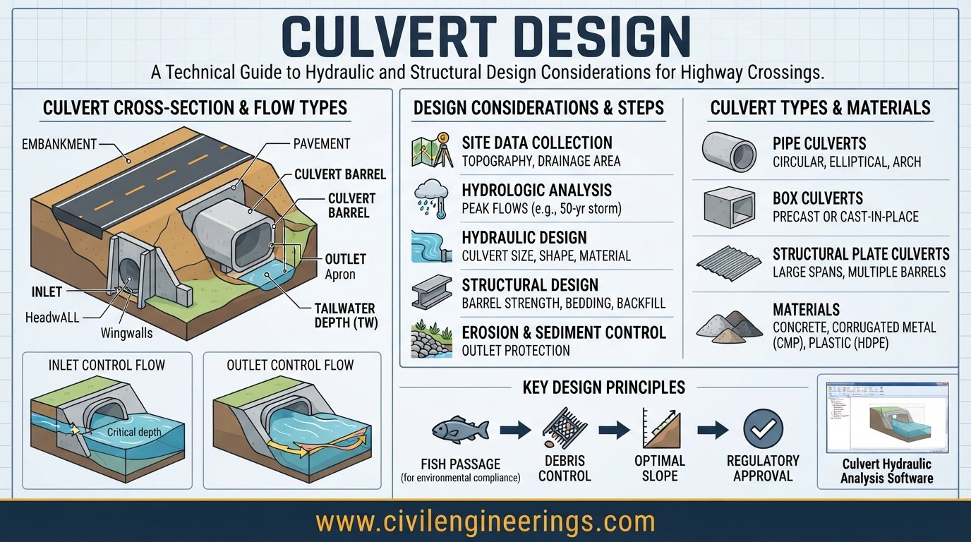
A road may look solid and continuous, but beneath the pavement, water must still move safely from one side to the other. That is where a properly planned Culvert Design becomes essential. A culvert is more than a pipe or concrete box placed under a road. It is a hydraulic and structural system that must carry design runoff, withstand traffic and earth loads, resist erosion, remain stable under changing groundwater conditions, and provide reliable service throughout its design life.
Poorly designed culverts can cause roadway flooding, embankment erosion, excessive upstream water levels, outlet scour, pavement failures, and even catastrophic road washouts. Good design therefore requires coordination between hydrology, hydraulics, structural engineering, geotechnical conditions, road geometry, construction methods, and maintenance requirements.
This guide explains the complete culvert design process, including types, site investigation, design discharge, hydraulic calculations, inlet and outlet control, structural considerations, scour protection, common mistakes, practical examples, and recommendations for engineers and contractors. The discussion also relates the process to commonly used IRC, AASHTO, FHWA, and ICE engineering practice.
What Is Culvert Design?
Culvert Design is the engineering process of selecting, sizing, analyzing, detailing, and constructing a drainage structure that safely conveys water beneath a road, railway, embankment, or similar obstruction.
A complete design normally addresses two major components:
- Hydraulic design — determines whether the culvert can safely convey the required discharge without excessive headwater, flooding, or damaging velocities.
- Structural design — determines whether the culvert can safely resist earth pressure, traffic loading, self-weight, water pressure, uplift, construction loads, and other applicable actions.
The FHWA Hydraulic Design Series No. 5 (HDS-5) treats culvert hydraulics through both inlet-control and outlet-control conditions and includes conventional and improved inlet configurations. (Federal Highway Administration)
A sound design also considers debris, sediment, erosion, maintenance access, environmental requirements, and the consequences of failure.


Types of Culverts Used in Highway Engineering
The selection of a culvert type depends on discharge, road geometry, available headroom, soil conditions, construction methods, hydraulic requirements, and cost.
Pipe Culverts
Pipe culverts are commonly used for relatively small drainage crossings. Circular reinforced concrete, corrugated metal, HDPE, and other approved pipe systems may be used depending on project specifications.
Advantages include:
- Simple installation
- Relatively low construction cost
- Availability of standard sizes
- Suitable performance for many small drainage crossings
However, designers must check inlet capacity, outlet velocity, bedding, joint performance, cover depth, and structural capacity.
Box Culverts
A box culvert normally consists of a reinforced-concrete rectangular cell with a top slab, bottom slab, and side walls.
Box culverts are particularly useful where:
- The required waterway is relatively wide.
- Vertical clearance is limited.
- A relatively flat hydraulic section is desirable.
- Reinforced concrete construction is appropriate.
- Multiple cells may be required.
For large highway drainage structures, single- or multi-cell box culverts can provide substantial hydraulic capacity while fitting beneath roadway embankments.
Arch and Other Special Culverts
Arch, elliptical, portal, and other special shapes may be selected when hydraulic, structural, environmental, or construction conditions justify them.
The selected shape should not be based solely on available cross-sectional area. Entrance geometry, hydraulic losses, structural behavior, construction requirements, and maintenance must also be considered.
Important Components of a Culvert
Understanding the individual components helps engineers identify potential failure points during design and construction.
Culvert Barrel
The barrel is the main enclosed water passage beneath the road.
Important parameters include:
- Barrel diameter or width
- Barrel height
- Length
- Longitudinal slope
- Material
- Roughness coefficient
- Entrance configuration
- Outlet configuration
Headwall
A headwall surrounds the culvert entrance or outlet and helps retain the embankment while providing a defined hydraulic transition.
Headwalls can also reduce erosion around the culvert ends. Highway agencies commonly combine the headwall with an apron and wingwalls.
Wingwalls
Wingwalls guide approaching flow toward the culvert entrance and retain the adjacent embankment.
Their geometry affects both structural stability and hydraulic performance.
Apron and Outlet Protection
An apron or other outlet treatment can help control erosion immediately downstream of the barrel. Depending on velocity and site conditions, designers may use riprap, concrete protection, stilling arrangements, gabions, or other energy-dissipation measures.
Cutoff Walls
Cutoff walls may be used where seepage, piping, undermining, or scour could threaten the structure.
They are especially important where the culvert passes through erodible soils or where hydraulic gradients are significant.
Site Investigation Before Culvert Design
A culvert should never be sized from rainfall data alone. Site conditions strongly influence the final design.
Before starting calculations, collect:
- Catchment area
- Catchment characteristics
- Existing drainage paths
- Topographic survey
- Road formation level
- Channel bed level
- Upstream and downstream invert levels
- Existing flood marks
- Tailwater conditions
- Soil profile
- Groundwater information
- Existing culverts and drainage structures
- Evidence of scour and erosion
- Debris and sediment conditions
- Utility locations
- Environmental constraints
The IRC:SP:13-2022 Guidelines for the Design of Small Bridges and Culverts specifically addresses site selection, collection of design data, flood discharge, scour, geometric requirements, structural details, hydraulics, protection works, and maintenance. (Indian Registry for Internet Names)
Field inspection is particularly valuable. A small drainage channel that appears insignificant during dry weather can carry substantial flows during intense storms.
Determining the Design Discharge
The design discharge is one of the most important inputs in culvert design.
Rational Method
For relatively small catchments where the method is appropriate, the Rational Method can be expressed in SI units as:
Where:
- = peak runoff, m³/s
- = runoff coefficient
- = rainfall intensity, mm/hour
- = catchment area, km²
The designer must select rainfall intensity corresponding to an appropriate duration and design frequency based on the governing standard and project requirements.
For larger or more complex watersheds, hydrologic modeling, regional regression relationships, unit hydrograph methods, or other approved procedures may be more appropriate.
Design Return Period
The design return period should not be selected simply because it is commonly used on another project.
It depends on:
- Road classification
- Consequences of failure
- Catchment characteristics
- Flood risk
- Regulatory requirements
- Structure importance
- Acceptable overtopping risk
- Local authority standards
IRC guidance includes provisions concerning design discharge and flood return periods for small bridges and culverts. (Scribd)
Hydraulic Design of a Culvert
Hydraulic design determines whether the selected culvert can pass the design flow while maintaining acceptable upstream and downstream conditions.
A typical design sequence is:
- Determine design discharge.
- Establish allowable headwater.
- Determine tailwater conditions.
- Select a trial culvert shape and size.
- Determine entrance configuration.
- Check inlet control.
- Check outlet control.
- Determine the governing condition.
- Check velocity and erosion.
- Evaluate road overtopping and flood risk.
- Provide inlet and outlet protection.
- Revise the design if required.
FHWA identifies a similar iterative design approach, with the designer determining whether inlet or outlet control governs each trial configuration. (Texas Department of Transportation)
Manning’s Equation
For flow conditions where Manning’s equation is applicable:
Where:
- = discharge
- = Manning roughness coefficient
- = flow area
- = hydraulic radius
- = energy slope or representative channel slope
The hydraulic radius is:
where is the wetted perimeter.
Manning’s equation is useful for evaluating open-channel portions of the hydraulic system, but a complete culvert analysis also needs to consider entrance losses, barrel losses, exit losses, transitions, tailwater, and control conditions.
Inlet Control vs Outlet Control
This is one of the most important concepts in Culvert Design.
Inlet Control
Under inlet control, the entrance geometry and available flow area primarily determine the culvert capacity.
Important factors include:
- Inlet shape
- Entrance edge geometry
- Headwater
- Culvert size
- Inlet configuration
- Barrel shape
An improved entrance can sometimes increase hydraulic efficiency without simply increasing barrel size. FHWA research demonstrates that inlet geometry can significantly influence box-culvert hydraulic performance. (Federal Highway Administration)
Outlet Control
Under outlet control, the barrel and downstream conditions have greater influence.
Factors include:
- Barrel length
- Barrel slope
- Hydraulic roughness
- Entrance loss
- Friction loss
- Exit loss
- Tailwater
- Barrel geometry
The designer must evaluate both conditions rather than assuming one will govern.
The governing condition is the one that produces the more restrictive hydraulic result for the design requirement.
Headwater and Tailwater Considerations
Headwater is the water level upstream of the culvert associated with the design flow.
Excessive headwater can cause:
- Upstream flooding
- Embankment saturation
- Roadway overtopping
- Damage to adjacent property
- Increased hydraulic loading
Tailwater is the downstream water level that can influence outlet hydraulics.
High tailwater can submerge the outlet and change the hydraulic behavior significantly. Therefore, downstream channel geometry and flood levels should be investigated instead of assuming free discharge.
Culvert Size Selection: Practical Example
Consider an illustrative drainage crossing with:
- Design discharge = 8 m³/s
- Trial box culvert = 2.0 m wide × 1.5 m high
- Approximate full-flow area = 3.0 m²
The approximate mean velocity if the full area carries the discharge would be:
This velocity alone does not prove that the culvert is adequately designed.
The engineer must still determine:
- Actual flow depth
- Inlet-control capacity
- Outlet-control headwater
- Tailwater elevation
- Barrel friction
- Entrance losses
- Outlet velocity
- Downstream erosion risk
- Structural adequacy
- Road overtopping condition
A hydraulic model or approved calculation procedure can then be used to refine the trial dimensions. FHWA’s HY-8 program is specifically intended to automate culvert hydraulic calculations and supports analysis based on HDS-5 methodologies. (Federal Highway Administration)


Structural Design of Culverts
Hydraulic adequacy does not guarantee structural safety.
A reinforced-concrete box culvert, for example, must be designed for the applicable combination of permanent, traffic, earth, hydraulic, and construction actions.
Major Structural Loads
Typical considerations include:
- Self-weight
- Earth fill
- Earth pressure
- Highway live load
- Surcharge
- Water pressure
- Uplift
- Construction loads
- Differential settlement
- Temperature effects where applicable
- Seismic actions where required
- Hydrostatic or buoyancy effects
The actual load combinations and design factors must follow the governing structural code.
For projects using Indian standards, IRC:SP:13-2022 points to limit-state design and the applicable IRC structural provisions, including IRC:112 for concrete structures. (Scribd)
Foundation and Geotechnical Design
The foundation must be compatible with the soil and groundwater conditions.
Investigate:
- Bearing capacity
- Settlement
- Differential settlement
- Soil classification
- Groundwater
- Expansive or collapsible soils
- Scour susceptibility
- Seepage
- Potential piping
A culvert can have excellent structural calculations and still fail if the foundation settles unevenly or the soil erodes beneath the structure.
Scour and Erosion Protection
Scour is one of the most common threats at culvert outlets.
High-velocity water can remove soil from:
- Culvert outlet
- Apron
- Channel bed
- Side slopes
- Wingwall foundations
- Embankment toes
The protection system should match the expected hydraulic conditions.
Possible measures include:
- Riprap
- Concrete aprons
- Gabions
- Reno mattresses
- Stilling basins
- Energy dissipators
- Outlet expansion
- Vegetated erosion-control systems where appropriate
FHWA maintains separate hydraulic guidance for energy dissipators and scour-related protection, while its HDS-5 culvert guidance also incorporates erosion, debris control, and special culvert considerations. (Federal Highway Administration)


Debris, Sediment, and Blockage
One of the biggest practical mistakes is designing only for clean-water hydraulic capacity.
Leaves, branches, trash, sediment, and other debris can partially or completely block a culvert inlet. FHWA’s culvert guidance includes specific consideration of debris control and maintenance. (Federal Highway Administration)
Designers should therefore consider:
- Upstream debris sources
- Vegetation
- Sediment transport
- Trash accumulation
- Inlet accessibility
- Cleaning requirements
- Trash racks or debris-control structures where justified
A debris-control device should not create a new blockage hazard or become impossible to maintain.
Culvert Inlet and Outlet Design
The inlet should transition flow into the barrel efficiently while minimizing undesirable separation and local erosion.
Common treatments include:
- Headwalls
- Wingwalls
- Flared entrances
- Beveled edges
- Aprons
- Improved hydraulic entrances
At the outlet, the design should provide a stable transition to the downstream channel.
The outlet arrangement should be checked for:
- Velocity
- Tailwater
- Scour
- Hydraulic jump potential
- Channel stability
- Bank erosion
The physical components of a typical headwall arrangement include the headwall, wingwalls, and apron, which also help retain the surrounding embankment.
Roadway Geometry and Culvert Placement
Culvert alignment should work with the natural drainage path wherever practical.
An unnecessarily skewed culvert can:
- Increase hydraulic losses
- Complicate construction
- Increase structural complexity
- Require larger wingwalls
- Create difficult maintenance conditions
The engineer should coordinate culvert location with:
- Horizontal road alignment
- Vertical profile
- Crossfall
- Embankment slope
- Existing watercourse
- Right-of-way
- Utilities
- Construction access
The final alignment should provide a stable hydraulic connection rather than simply placing the culvert at the shortest geometric crossing.
Construction and Quality Control
Even a well-designed culvert can fail because of poor construction.
Bedding and Foundation Preparation
The foundation should be properly prepared and compacted. Unsuitable material should be removed or treated according to the geotechnical design.
Concrete Quality
For reinforced concrete culverts, control:
- Concrete strength
- Slump
- Water-cement ratio
- Reinforcement placement
- Cover
- Formwork
- Curing
- Construction joints
Backfilling
Backfill should be placed in controlled layers and compacted uniformly on both sides of box structures.
Unequal lateral backfilling can generate undesirable structural stresses and movement.
Pipe Culvert Installation
For pipe culverts, pay particular attention to:
- Bedding
- Line and grade
- Joint integrity
- Haunch support
- Backfill compaction
- Cover depth
Construction inspection should verify the actual installation against the approved drawings rather than relying only on final visual inspection.
IRC, AASHTO, FHWA, and ICE References
There is no single universal culvert design procedure that should be copied onto every project. The governing road authority and adopted design standards control the final criteria.
IRC
For Indian highway projects, IRC:SP:13-2022, Guidelines for the Design of Small Bridges and Culverts, is an important reference covering design data, discharge, scour, hydraulic considerations, structural details, protection, and maintenance. (Indian Registry for Internet Names)
AASHTO
For projects designed under U.S. practice, AASHTO provisions should be used for applicable structural and highway design requirements, together with the relevant agency hydraulic criteria.
FHWA
HDS-5, Hydraulic Design of Highway Culverts remains a major reference for culvert hydraulics. FHWA also provides HY-8 for culvert hydraulic analysis. (Federal Highway Administration)
ICE
The Institution of Civil Engineers provides broader professional guidance and engineering knowledge relevant to hydraulic structures, highways, risk, sustainability, and infrastructure asset management. For a specific project, however, the applicable national highway, drainage, structural, and environmental standards should take precedence.
Common Culvert Design Mistakes
Several errors repeatedly appear in poorly planned drainage projects.
Designing Only for the Pipe or Box Size
A larger opening does not automatically solve every hydraulic problem. Entrance conditions, tailwater, slope, roughness, and outlet conditions can govern.
Ignoring Downstream Conditions
A culvert outlet should connect to a stable downstream channel. Discharging a high-velocity jet onto an unprotected soil bank is a common cause of failure.
Using an Inappropriate Return Period
The design flood should reflect the importance and risk associated with the road rather than an arbitrary standard value.
Ignoring Debris
A culvert that works perfectly under clean-water conditions may fail when its entrance becomes blocked.
Poor Backfill Compaction
Structural distress and settlement can occur when construction quality does not match the design assumptions.
Neglecting Maintenance
A culvert needs to remain accessible for inspection, debris removal, sediment clearance, and erosion monitoring.
Best Practices for Culvert Design
A reliable design should follow these principles:
- Start with a detailed site investigation.
- Delineate the contributing catchment accurately.
- Establish a defensible design discharge.
- Check both inlet and outlet control.
- Evaluate headwater and tailwater.
- Consider debris and sediment.
- Check outlet velocity and scour.
- Provide appropriate erosion protection.
- Coordinate hydraulic and structural design.
- Investigate foundation conditions.
- Account for construction sequencing.
- Provide practical maintenance access.
- Evaluate roadway overtopping risk.
- Use approved hydraulic software as a design aid rather than blindly accepting software output.
- Document assumptions, input data, calculations, and design criteria.
FHWA currently lists HDS-5 as its principal highway culvert hydraulic publication and HY-8 as its culvert hydraulic analysis software. (Federal Highway Administration)
Practical Recommendations for Students, Engineers, and Contractors
For Civil Engineering Students
Do not memorize culvert formulas without understanding the physical system.
Focus on:
- Continuity
- Energy principles
- Manning’s equation
- Critical flow
- Headwater
- Tailwater
- Inlet control
- Outlet control
- Scour
- Basic structural behavior
Practice complete design examples from catchment analysis through outlet protection.
For Highway Engineers and Consultants
Always connect hydraulic calculations with the actual site.
Review:
- Survey data
- Flood history
- Existing drainage behavior
- Geotechnical reports
- Hydraulic model assumptions
- Road overtopping consequences
- Maintenance requirements
A computer-generated result is only as reliable as the input data and engineering assumptions.
For Contractors
Construction quality directly affects culvert performance.
Pay particular attention to:
- Foundation preparation
- Correct line and grade
- Reinforcement placement
- Concrete quality
- Pipe bedding
- Joint sealing
- Layered backfilling
- Compaction
- Headwall construction
- Outlet protection
Do not change culvert levels, dimensions, or outlet details in the field without engineering approval.
Frequently Asked Questions About Culvert Design
1. What is the main purpose of a culvert?
A culvert conveys water beneath a road, railway, embankment, or similar obstruction while maintaining the required structural and hydraulic performance.
2. How is culvert size determined?
Culvert size is determined from the design discharge, allowable headwater, tailwater, inlet geometry, barrel characteristics, slope, roughness, site conditions, and applicable design standards.
3. What is the difference between inlet control and outlet control?
Inlet control occurs when the entrance primarily limits discharge capacity. Outlet control occurs when barrel losses, length, slope, tailwater, and other downstream conditions have greater influence.
4. Is Manning’s equation sufficient for culvert design?
No. Manning’s equation is useful for specific flow conditions, but complete culvert design requires consideration of entrance losses, control conditions, headwater, tailwater, barrel hydraulics, outlet conditions, and erosion.
5. Why is headwater important?
Excessive headwater can cause upstream flooding, embankment saturation, roadway overtopping, and increased hydraulic loading.
6. Why do culverts require wingwalls?
Wingwalls can retain the road embankment and guide water smoothly toward or away from the culvert opening. Their geometry also affects hydraulic performance.
7. Why is scour protection needed at a culvert outlet?
Water leaving a culvert can have sufficient velocity to erode the downstream channel. Riprap, aprons, energy dissipators, or other protection systems can reduce this risk.
8. Can a larger culvert always solve flooding problems?
No. Flooding may result from inadequate upstream drainage, blocked entrances, high tailwater, poor alignment, downstream restrictions, or an inadequate design discharge. Simply increasing barrel size may not address the controlling problem.
9. What software can be used for hydraulic culvert analysis?
FHWA’s HY-8 is a widely used culvert hydraulic analysis program. It automates hydraulic calculations and is associated with FHWA HDS-5 methodology. (Federal Highway Administration)
10. Which standard should be followed for culvert design?
The applicable project authority determines the governing standard. Indian projects may use relevant IRC provisions; U.S. projects commonly rely on AASHTO and applicable agency/FHWA guidance. Local drainage, structural, environmental, and highway requirements should always be checked.
Conclusion
Effective Culvert Design requires much more than selecting a pipe diameter or concrete box dimension. A safe culvert must work as an integrated hydraulic, structural, geotechnical, and roadway system. Engineers need to determine a reliable design discharge, understand the catchment, evaluate inlet and outlet control, establish acceptable headwater and tailwater conditions, and protect both the culvert and downstream channel from erosion.
Structural performance is equally important. Foundation conditions, earth pressure, traffic loads, reinforcement, settlement, uplift, construction quality, and long-term durability all influence the service life of the structure. Debris, sediment, maintenance access, and environmental considerations should also be incorporated during the design stage rather than treated as afterthoughts.
For professional projects, use the governing national and agency standards together with recognized hydraulic guidance such as FHWA HDS-5, applicable IRC provisions, AASHTO requirements, and project-specific engineering criteria. A well-designed culvert should not merely pass water during an ordinary storm; it should provide dependable performance under the range of conditions for which the roadway was designed.

Kamran Malik is a passionate civil engineering writer and researcher who specializes in construction, transportation, structural engineering, and infrastructure topics. Through his articles on CivilEngineerings.com, he simplifies complex engineering concepts and shares practical insights, industry trends, and educational resources for students, professionals, and engineering enthusiasts.
Thank you—I love data!!!!