
Introduction
Surveying forms the backbone of every successful civil engineering project. Engineers rely on accurate measurements before they design highways, bridges, buildings, railways, canals, or drainage systems. Among the many surveying methods, Compass Survey stands out as one of the simplest and most economical techniques for determining the direction of survey lines.
A compass survey uses magnetic bearings instead of angles measured by sophisticated instruments. This method allows surveyors to establish the relative positions of points quickly, especially in areas where high precision is not essential. Although modern technologies such as GPS, Total Stations, and drones dominate large infrastructure projects, compass surveying continues to play an important role in preliminary investigations, route reconnaissance, forest surveys, and highway planning.
Understanding Compass Survey helps civil engineers, road engineers, contractors, and engineering students develop a strong foundation in field surveying. This guide explains its principles, equipment, bearings, engineering applications, practical examples, and best practices in a simple yet technically accurate manner.
What is Compass Survey?
Compass Survey is a surveying method that determines the direction of survey lines by measuring magnetic bearings with a compass while measuring distances with a chain or measuring tape.
Unlike theodolite surveying, which measures horizontal angles, compass surveying depends on the Earth’s magnetic field to establish line directions.
Surveyors commonly use this method for:
- Preliminary road surveys
- Highway route reconnaissance
- Canal alignment
- Forest mapping
- Small land surveys
- Topographic investigations
- Property boundary surveys
Compass surveying delivers quick results with minimal equipment, making it suitable for projects where moderate accuracy meets engineering requirements.
Why Compass Survey is Important
Compass surveying remains valuable because it combines simplicity, speed, and affordability.
Road engineers often perform reconnaissance surveys before selecting a highway alignment. During this stage, they need a rapid method to determine the direction of possible routes through hills, forests, agricultural land, or undeveloped terrain.
Major Benefits
- Requires simple equipment
- Saves surveying time
- Reduces project costs
- Supports preliminary engineering studies
- Performs well in rough terrain
- Helps prepare route maps
Even though advanced surveying technologies have become widely available, engineers still teach compass surveying because it strengthens fundamental surveying knowledge.
Principles of Compass Survey
Compass surveying follows a straightforward engineering principle.
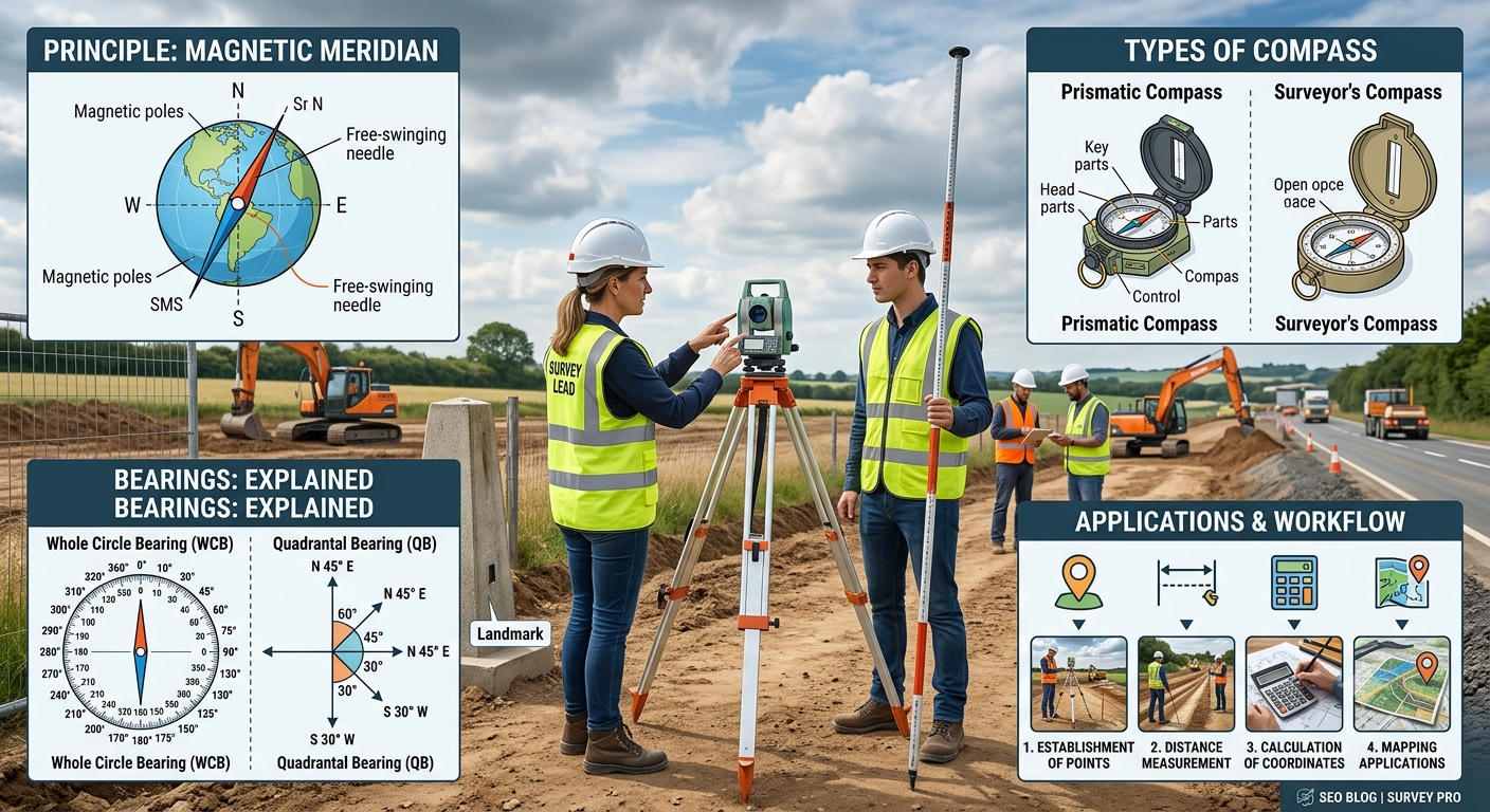
A freely suspended magnetic needle aligns itself with the Earth’s magnetic field. Surveyors use this magnetic north direction as a reference to measure the bearing of every survey line.
The survey process consists of two basic measurements:
- Direction of the line (bearing)
- Length of the line (distance)
Combining these measurements allows surveyors to calculate the relative positions of different stations and prepare an accurate plan.
Basic Principle Diagram
                 Magnetic North
                      ↑
                      │
                      │
        Station A •────────────► Station B
                Bearing = 65°
                Distance = 120 m
Every survey line has:
- One bearing
- One measured distance
Together, these values define the location of each survey station.
Components of a Compass
A surveying compass contains several parts that help measure bearings accurately.
1. Magnetic Needle
The magnetic needle always points toward magnetic north and serves as the primary reference for measuring bearings.
2. Graduated Circle
The graduated circle displays bearings in degrees.
Depending on the compass type, it may measure:
- 0°–360° (Whole Circle Bearing)
- 0°–90° (Quadrantal Bearing)
3. Prism
A prismatic compass includes a prism that allows surveyors to read bearings while simultaneously sighting the survey line.
This feature improves speed and reduces observation errors.
4. Sighting Vanes
Surveyors use the sighting vanes to align the compass precisely with the survey station.
Proper alignment improves measurement accuracy.
5. Compass Box
The compass box protects the magnetic needle and supports smooth needle movement during observations.
Types of Compass Survey
Civil engineers mainly use two types of compass surveying instruments.
1. Prismatic Compass Survey
The prismatic compass is the most popular instrument in engineering surveys.
It measures Whole Circle Bearings (WCB) ranging from 0° to 360° in a clockwise direction.
Characteristics
- High portability
- Faster observations
- Better readability
- Simultaneous sighting and reading
- Suitable for reconnaissance surveys
Common Applications
- Highway route surveys
- Railway reconnaissance
- Canal surveys
- Forest engineering
2. Surveyor’s Compass Survey
The surveyor’s compass measures Quadrantal Bearings (QB).
Bearings begin from either North or South and extend toward East or West.
Example Bearings
- N 35° E
- N 60° W
- S 20° E
- S 75° W
Surveyor’s compasses suit educational surveys and small property measurements.
Types of Bearings in Compass Survey
Bearings describe the direction of a survey line relative to magnetic north.
Surveyors generally use two bearing systems.
Whole Circle Bearing (WCB)
Whole Circle Bearings measure angles clockwise from magnetic north.
Range:
0° to 360°
Examples
- 40°
- 110°
- 220°
- 315°
Whole Circle Bearing Diagram
               N (0°)
                 │
       315°      │      45°
            \     │     /
W (270°)─────●────┼─────E (90°)
            /     │
       225°       │      135°
                 │
             S (180°)
Quadrantal Bearing (QB)
Quadrantal Bearings measure angles from North or South toward East or West.
Examples include:
- N 40° E
- N 20° W
- S 35° E
- S 60° W
Surveyors often use this system in cadastral and property surveys.
Fore Bearing and Back Bearing
Every survey line has two bearings.
Fore Bearing (FB)
The fore bearing measures the direction from the first station to the next station.
Example:
A → B
Bearing = 80°
Back Bearing (BB)
The back bearing measures the same line in the opposite direction.
B → A
Bearing = 260°
Relationship
For Whole Circle Bearings:
- Add 180° when the fore bearing is less than 180°.
- Subtract 180° when the fore bearing exceeds 180°.
Illustration
A ●──────────────► B

Fore Bearing = 80°

B ◄──────────────● A

Back Bearing = 260°
Checking fore and back bearings helps surveyors detect local magnetic attraction and observational errors.
Magnetic Meridian and True Meridian
Understanding reference directions is essential in compass surveying.
Magnetic Meridian
A magnetic meridian follows the direction indicated by the magnetic needle.
This direction changes slightly over time because the Earth’s magnetic field shifts continuously.
True Meridian
A true meridian follows the geographic North Pole and remains independent of magnetic influences.
Modern GPS receivers and satellite-based surveying systems typically reference the true meridian.
Comparison Table
| Feature | Magnetic Meridian | True Meridian |
|---|---|---|
| Reference | Magnetic North | Geographic North |
| Stability | Changes over time | Nearly constant |
| Instrument | Compass | Astronomical or GPS observations |
| Accuracy | Moderate | High |
Practical Engineering Example
A road engineering team plans a new rural highway connecting two villages. Before carrying out a detailed topographic survey, the engineers perform a reconnaissance survey using a prismatic compass.
They establish several survey stations along the proposed alignment and measure the magnetic bearings and distances between each point. The collected field data helps identify feasible routes, estimate earthwork requirements, locate stream crossings, and avoid steep slopes. After completing this preliminary investigation, the design team conducts detailed surveys using Total Stations and GPS equipment for final engineering design.
This practical workflow demonstrates how Compass Survey supports early decision-making while reducing time and investigation costs during highway planning.
Step-by-Step Compass Survey Procedure
A systematic field procedure improves the accuracy and efficiency of a compass survey. Every observation should follow a logical sequence to reduce human error and ensure reliable field data.
Step 1: Reconnaissance Survey
Begin with a reconnaissance survey to understand the site conditions.
During this stage, the surveyor should:
- Walk through the entire survey area.
- Identify suitable survey stations.
- Check visibility between stations.
- Prepare a rough field sketch.
A good reconnaissance survey saves time during the actual fieldwork.
Step 2: Select Survey Stations
Choose stations that provide clear lines of sight between consecutive points.
A suitable station should:
- Offer stable ground.
- Remain free from obstructions.
- Avoid magnetic interference.
- Allow convenient distance measurements.
Survey Layout Diagram
Station A ───────── Station B ───────── Station C
      │                                   │
      └──────────── Station D ────────────┘
Step 3: Set Up the Compass
Place the compass on a tripod or hold it steadily at the survey station.
Ensure that:
- The compass remains level.
- The magnetic needle moves freely.
- No nearby metallic objects affect the reading.
Wait until the needle stabilizes before taking observations.
Step 4: Measure the Bearing
Align the sighting vane with the next survey station.
Read the magnetic bearing carefully and record it immediately in the field book.
Repeat the observation if the reading appears inconsistent.
Step 5: Measure the Distance
Measure the horizontal distance between stations using:
- Steel tape
- Survey chain
- Electronic Distance Measurement (EDM), when available
Record every measurement accurately.
Step 6: Observe the Back Bearing
Move to the next station and observe the back bearing of the previous line.
Compare the fore bearing and back bearing.
If the difference differs from 180°, investigate possible magnetic attraction or observational errors.
Step 7: Complete the Traverse
Repeat the same procedure for all remaining stations until the traverse closes.
After completing the survey:
- Check field notes.
- Verify measurements.
- Plot the survey.
- Calculate corrections if necessary.
Common Errors in Compass Survey
Every surveying method contains potential sources of error. Understanding these errors helps engineers improve field accuracy.
1. Magnetic Errors
Nearby metallic objects, vehicles, electrical cables, or machinery can disturb the magnetic needle.
Examples
- Steel bridges
- Railway tracks
- Power transmission lines
- Reinforcement bars
- Heavy construction equipment
Prevention
Keep the compass away from magnetic objects whenever possible.
2. Instrumental Errors
Poor instrument condition may produce inaccurate readings.
Examples include:
- Bent needle
- Damaged prism
- Loose sight vane
- Worn graduations
Regular inspection and calibration reduce these errors.
3. Personal Errors
Human mistakes often contribute to inaccurate observations.
Common mistakes include:
- Incorrect sighting
- Reading the wrong graduation
- Recording incorrect values
- Poor leveling
- Careless distance measurement
Practice and proper supervision improve field performance.
4. Natural Errors
Environmental conditions can influence observations.
Examples include:
- Strong winds
- Temperature variations
- Magnetic storms
- Uneven terrain
- Poor visibility
Surveyors should avoid taking observations during unfavorable conditions whenever practical.
Advantages of Compass Survey
Compass surveying offers several practical benefits, particularly during preliminary engineering investigations.
Major Advantages
- Simple field procedure
- Low equipment cost
- Fast observations
- Easy transportation
- Suitable for rough terrain
- Minimal manpower requirements
- Ideal for reconnaissance surveys
- Useful for preliminary road alignment studies
Because of these advantages, engineers often use compass surveys during the early stages of infrastructure planning.
Disadvantages of Compass Survey
Despite its usefulness, compass surveying has several limitations.
Major Limitations
- Lower accuracy than theodolite surveys
- Sensitive to magnetic interference
- Unsuitable for high-precision engineering work
- Difficult to use near electrical installations
- Magnetic declination affects bearings
- Requires frequent accuracy checks
Modern highway construction projects usually combine compass surveys with Total Stations, GNSS, or GPS equipment to achieve higher precision.
Applications of Compass Survey in Road Engineering
Compass surveying remains valuable in several stages of road and highway development.
1. Route Reconnaissance
Engineers use compass surveys to identify feasible highway corridors before detailed investigations begin.
2. Preliminary Highway Alignment
Compass bearings help establish temporary centerlines for route comparison.
3. Canal and Pipeline Surveys
Surveyors determine the direction of proposed alignments quickly in open terrain.
4. Forest Road Development
Compass surveying performs well in heavily vegetated areas where rapid reconnaissance is required.
5. Rural Infrastructure Projects
Small access roads, farm roads, and village streets often begin with compass-based preliminary surveys.
Practical Highway Example
A transportation department plans a new bypass around a growing town. During the reconnaissance stage, the survey team uses a prismatic compass to compare three alternative alignments. By combining bearing measurements with approximate distances, the team identifies the shortest route with gentle terrain and fewer stream crossings. Detailed GPS and Total Station surveys then refine the selected alignment for final design.
Engineering Best Practices
Professional surveyors follow established procedures to improve the reliability of compass surveys.
Recommended Practices
- Perform a reconnaissance survey before field measurements.
- Inspect the compass before every survey.
- Avoid magnetic interference from nearby metal objects.
- Record field observations immediately.
- Measure both fore and back bearings.
- Verify station locations before leaving the site.
- Repeat important observations for confirmation.
- Maintain clear and organized field notes.
- Protect instruments during transportation.
- Cross-check compass data with modern surveying equipment whenever possible.
These practices reduce errors and improve the quality of engineering decisions.
Practical Recommendations
Civil Engineers
- Use compass surveys during route selection and preliminary planning.
- Verify magnetic bearings with GPS or Total Station data where higher accuracy is required.
- Consider local magnetic declination during project planning.
Contractors
- Train survey crews in proper compass handling techniques.
- Protect surveying instruments from damage and moisture.
- Avoid storing compasses near magnetic tools and equipment.
Engineering Students
- Practice measuring bearings in different field conditions.
- Learn the relationship between fore bearings and back bearings.
- Understand the limitations of magnetic surveying.
- Compare compass surveys with modern digital surveying methods to appreciate their strengths and weaknesses.
General Discussion of IRC, AASHTO, and ICE Practices
Although modern infrastructure projects primarily rely on advanced surveying technologies, engineering organizations such as IRC, AASHTO, and ICE emphasize the importance of accurate survey data during the planning and design stages.
General engineering principles include:
- Carry out thorough reconnaissance before detailed surveys.
- Establish reliable horizontal and vertical control points.
- Verify field measurements through independent checks.
- Select surveying methods that match the required project accuracy.
- Maintain complete survey documentation for future reference.
- Integrate traditional field techniques with modern digital surveying systems when appropriate.
Following these principles improves project quality, reduces construction risks, and supports efficient highway design.
Frequently Asked Questions (FAQs)
1. What is a Compass Survey?
A Compass Survey is a surveying method that determines the direction of survey lines using magnetic bearings while measuring distances with a chain or tape.
2. Where is Compass Survey commonly used?
Engineers commonly use it for preliminary road surveys, route reconnaissance, forest surveys, canal projects, property surveys, and small-scale topographic mapping.
3. What is the difference between a prismatic compass and a surveyor’s compass?
A prismatic compass measures Whole Circle Bearings (0°–360°), while a surveyor’s compass measures Quadrantal Bearings using north or south as the reference.
4. What are Fore Bearing and Back Bearing?
The Fore Bearing measures the direction from one station to the next, whereas the Back Bearing measures the same line in the opposite direction.
5. Why does magnetic declination affect Compass Survey?
Magnetic declination is the angle between true north and magnetic north. If surveyors ignore it, bearing measurements may differ from the true direction.
6. What causes local magnetic attraction?
Nearby steel structures, vehicles, power lines, railway tracks, reinforced concrete, and heavy machinery can influence the magnetic needle and produce incorrect readings.
7. What equipment is required for a Compass Survey?
The basic equipment includes a compass (prismatic or surveyor’s), tripod, ranging rods, chain or steel tape, arrows, pegs, and a field book.
8. Is Compass Survey suitable for highway construction?
Compass surveying is suitable for reconnaissance and preliminary alignment studies. Engineers generally use Total Stations, GNSS, and GPS for detailed highway surveys.
9. How can surveyors improve the accuracy of a Compass Survey?
They can improve accuracy by selecting suitable stations, avoiding magnetic interference, checking fore and back bearings, repeating critical observations, and maintaining accurate field notes.
10. Is Compass Survey still relevant today?
Yes. Although advanced digital surveying equipment dominates modern engineering, Compass Survey remains valuable for education, preliminary investigations, route planning, and remote-area reconnaissance.
Conclusion
Compass Survey remains one of the most practical and fundamental surveying methods in civil and highway engineering. It provides a simple, economical, and efficient way to determine the direction of survey lines during preliminary investigations, route reconnaissance, and small-scale engineering projects. By understanding magnetic bearings, compass components, surveying procedures, and common sources of error, engineers can collect reliable field data that supports better planning and decision-making. While modern technologies such as Total Stations, GNSS, drones, and GPS deliver higher precision, Compass Survey continues to play an important role in engineering education and early project development. Following recognized engineering practices, maintaining accurate field records, and combining traditional surveying techniques with modern equipment allow professionals to achieve dependable results. Mastering Compass Survey equips engineers, contractors, and students with essential field skills that form the foundation of successful infrastructure and road engineering projects.

Kamran Malik is a passionate civil engineering writer and researcher who specializes in construction, transportation, structural engineering, and infrastructure topics. Through his articles on CivilEngineerings.com, he simplifies complex engineering concepts and shares practical insights, industry trends, and educational resources for students, professionals, and engineering enthusiasts.