
Introduction
Every successful road, highway, railway, or infrastructure project begins with a well-planned design that accurately represents real-world conditions before construction starts. Modern transportation projects no longer rely solely on traditional 2D drawings. Instead, engineers use intelligent three-dimensional models to improve design accuracy, reduce construction risks, optimize earthwork, and simplify project coordination. One of the most valuable technologies enabling this transformation is Corridor Modeling.
Corridor Modeling has become an essential component of highway engineering, transportation planning, and Building Information Modeling (BIM). It allows engineers to create dynamic road models by combining alignments, profiles, assemblies, and terrain data into a single intelligent corridor. As project requirements change, the entire design updates automatically, saving countless hours while minimizing costly design errors.
In this comprehensive guide, you’ll learn what Corridor Modeling is, how it works, its key components, engineering principles, workflow, practical applications, benefits, limitations, and industry best practices. Whether you are a civil engineering student, highway engineer, consultant, contractor, researcher, or government professional, this article will provide practical knowledge that can be applied to real-world transportation infrastructure projects.
What is Corridor Modeling?
Corridor Modeling is a digital engineering process used to create an intelligent three-dimensional representation of linear infrastructure such as highways, roads, railways, canals, pipelines, and utility corridors.
Instead of drawing individual road sections manually, engineers define the road’s geometry using several interconnected design elements. The software then generates a complete corridor model that automatically updates whenever one of these elements changes.
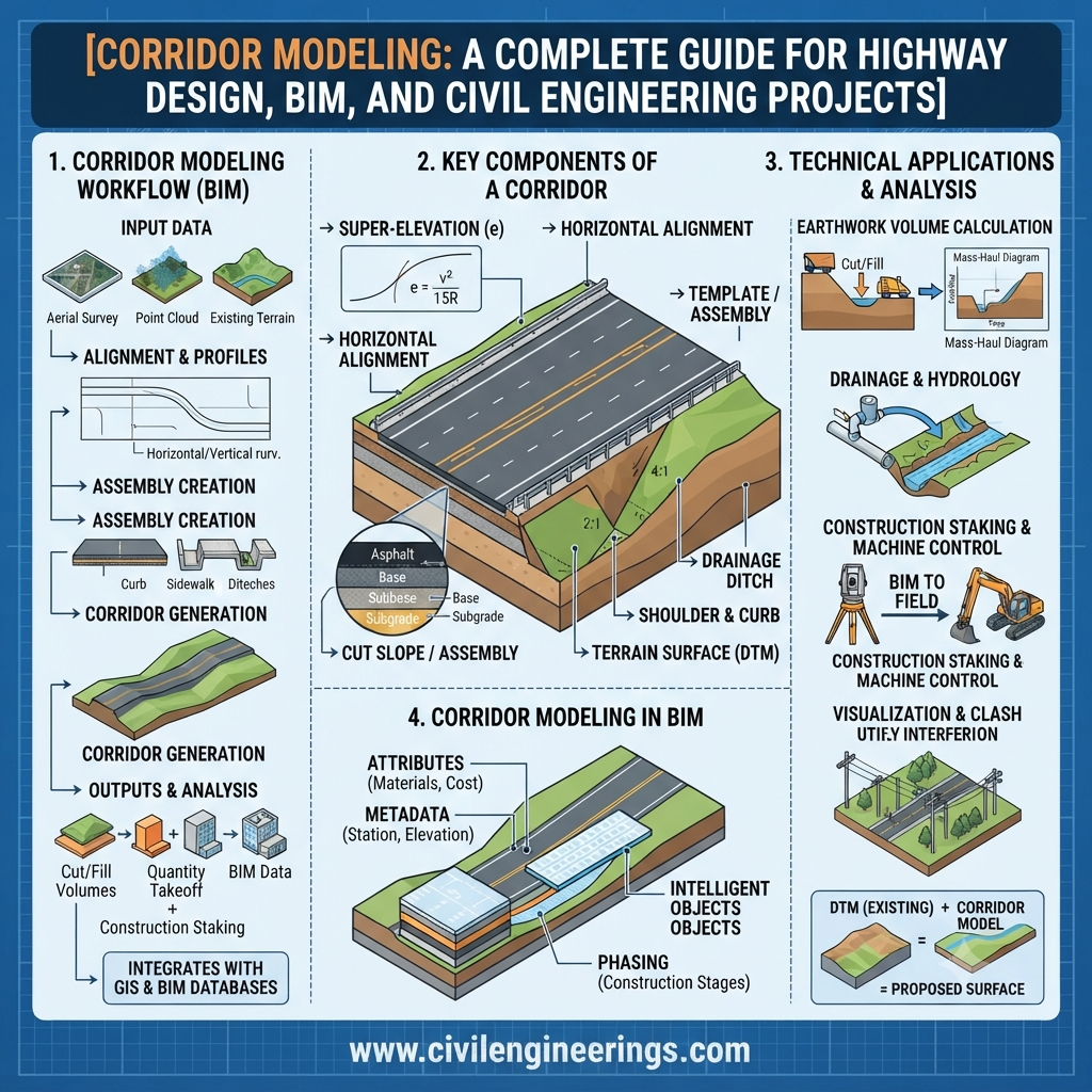
A corridor model typically combines:
- Horizontal alignment
- Vertical profile
- Cross-sectional assemblies
- Existing ground surface
- Design parameters
- Material layers
- Earthwork calculations
The result is an accurate and dynamic infrastructure model that supports planning, design, construction, and maintenance throughout the project lifecycle.
Unlike conventional CAD drawings, corridor models are intelligent. Every modification to the alignment, profile, or assembly is reflected automatically across the entire model, improving efficiency and reducing design inconsistencies.
Why Corridor Modeling is Important
Modern transportation projects involve thousands of design decisions. Even a minor adjustment to road alignment can affect drainage, earthwork quantities, structures, utilities, right-of-way, and construction costs.
Corridor Modeling addresses these challenges by creating a single coordinated design environment.
Its importance includes:
- Improves design accuracy
- Reduces manual drafting
- Minimizes engineering errors
- Speeds up project delivery
- Supports BIM implementation
- Enhances collaboration
- Produces accurate quantity estimates
- Simplifies design revisions
- Improves visualization
- Optimizes earthwork balancing
Large highway agencies increasingly require digital corridor models because they improve project coordination among designers, contractors, surveyors, and construction managers.
Evolution of Corridor Modeling in Highway Engineering
Road design has evolved significantly over the past several decades.
Traditional Design Era
Earlier highway projects relied on:
- Paper drawings
- Manual calculations
- Hand-drafted cross sections
- Separate plan and profile sheets
- Manual earthwork estimation
Updating a design often required revising hundreds of drawings manually, increasing both time and cost.
CAD-Based Design
Computer-Aided Design (CAD) introduced digital drafting, improving productivity while reducing repetitive work.
However, CAD drawings remained largely static. Engineers still needed to update many design elements individually whenever project geometry changed.
Intelligent Corridor Modeling
Today’s infrastructure projects use intelligent corridor models where all geometric components remain interconnected.
If engineers modify:
- Road width
- Shoulder slope
- Centerline alignment
- Vertical profile
- Pavement thickness
the corridor automatically regenerates, ensuring consistency throughout the project.
This capability has transformed highway engineering and supports digital delivery requirements adopted by many transportation authorities worldwide.
Fundamental Engineering Principles
Successful Corridor Modeling depends on several core engineering concepts.
Geometric Design
The corridor follows established geometric design standards that define:
- Design speed
- Horizontal curves
- Vertical curves
- Superelevation
- Lane width
- Shoulder width
- Cross slope
- Sight distance
Proper geometric design ensures safety, comfort, and efficient traffic movement.
Terrain Modeling
Accurate terrain data forms the foundation of every corridor model.
Survey information is collected using:
- Total stations
- GNSS surveys
- Drone mapping
- LiDAR scanning
- Mobile mapping systems
The existing ground surface is converted into a Digital Terrain Model (DTM) or Triangulated Irregular Network (TIN), which serves as the reference for corridor creation.
Parametric Design
Modern corridor models use parametric engineering.
Instead of manually editing every cross section, engineers define parameters such as:
- Lane width
- Pavement depth
- Side slope
- Ditch geometry
- Shoulder width
Changing one parameter automatically updates the entire corridor model.
Surface Modeling
Multiple surfaces can exist simultaneously, including:
- Existing ground
- Proposed road surface
- Subgrade
- Finished grade
- Pavement layers
These surfaces support quantity calculations, drainage analysis, and construction planning.
Key Components of Corridor Modeling
Understanding each component is essential for creating accurate highway models.
1. Alignment
The alignment defines the horizontal path of the road.
It includes:
- Tangents
- Circular curves
- Spiral transitions
- Stationing
- Control points
The alignment acts as the backbone of the corridor.
2. Profile
The profile represents the vertical geometry of the roadway.
It includes:
- Existing ground profile
- Proposed profile
- Vertical curves
- Grades
- Elevations
- High and low points
The profile determines how the road rises and falls across the landscape.
3. Assembly
An assembly represents the typical roadway cross-section.
A highway assembly may include:
- Traffic lanes
- Median
- Shoulder
- Kerb
- Sidewalk
- Drainage ditch
- Embankment slope
- Pavement layers
Assemblies define what the road looks like at each station.
4. Subassembly
Subassemblies are the individual components that make up an assembly.
Examples include:
- Lane
- Shoulder
- Side slope
- Curb
- Barrier
- Sidewalk
- Retaining wall
- Ditch
These modular elements can be reused across multiple projects, improving design efficiency and consistency.
5. Targets
Targets control how corridor components react to external design conditions.
Common targets include:
- Existing ground
- Feature lines
- Polylines
- Offset alignments
- Elevation targets
For example, an embankment slope can automatically extend until it intersects the existing terrain, eliminating the need for manual adjustments.
6. Surface
Surfaces define the terrain and proposed design elevations within the model.
Typical corridor surfaces include:
- Existing Ground (EG)
- Finished Grade (FG)
- Subgrade
- Top of Pavement
- Datum Surface
Engineers use these surfaces for cut-and-fill calculations, drainage design, clash detection, and construction staking.
7. Corridor
The corridor is the final integrated model created by combining:
- Horizontal alignment
- Vertical profile
- Assembly
- Surface
- Targets
It generates a continuous 3D representation of the infrastructure that updates dynamically whenever any source element changes.
Simplified Corridor Modeling Diagram
           Existing Ground Surface
      ~~~~~~~~~~~~~~~~~~~~~~~~~~~~~~~~~~

                ▲
                │ Target Surface
                │
--------------------------------------------  Proposed Road Surface
        | Lane | Median | Lane |
        |______|________|______|
          \                  /
           \                /
            \______________/
             Pavement Layers
                 Subgrade
                  Fill/Cut

      Alignment + Profile + Assembly
                 │
                 ▼
          Intelligent Corridor Model
The corridor serves as the central digital model from which cross-sections, quantity reports, earthwork volumes, visualization outputs, and construction documentation can all be generated.
How Corridor Modeling Works (Step-by-Step)
Creating a corridor model follows a structured engineering workflow to ensure accuracy and consistency.
Step 1: Collect Survey Data
The process begins with gathering precise topographic information using field surveys, GNSS, LiDAR, drones, or conventional total station methods. This data is used to develop the existing ground surface that forms the foundation of the design.
Step 2: Create the Horizontal Alignment
Engineers define the road centerline by laying out tangents, curves, transition spirals, and stationing in accordance with the selected design standards. The alignment determines the roadway’s path across the terrain.
Step 3: Develop the Vertical Profile
Once the alignment is established, a vertical profile is designed to satisfy grading requirements, drainage considerations, vehicle performance, and safety criteria. Vertical curves are introduced to provide smooth transitions between grades.
Step 4: Build the Assembly
The assembly represents the standard cross-section of the roadway. It is created by combining multiple subassemblies such as travel lanes, shoulders, medians, kerbs, sidewalks, drainage channels, retaining walls, and embankment slopes. Different assemblies can be assigned to different stations to accommodate changes in terrain or roadway configuration.
Step 5: Assign Targets
Target mapping connects corridor components to external objects such as existing ground surfaces, feature lines, offset alignments, or daylight lines. This enables side slopes, ditches, and other elements to adjust automatically to changing site conditions.
Step 6: Generate the Corridor
Once the alignment, profile, assemblies, and targets are linked, the software creates the complete three-dimensional corridor. The model updates dynamically whenever a design parameter changes, eliminating repetitive drafting work.
Step 7: Create Corridor Surfaces
The corridor generates several design surfaces, including:
- Finished Ground Surface
- Top of Pavement
- Datum Surface
- Subgrade Surface
- Pavement Layer Surfaces
These surfaces support earthwork calculations, drainage analysis, and construction planning.
Step 8: Produce Engineering Deliverables
The completed corridor model can automatically generate:
- Plan and profile sheets
- Cross sections
- Earthwork reports
- Quantity take-offs
- Material volumes
- Machine control models
- BIM deliverables
- Construction drawings
Corridor Modeling Workflow
A typical highway corridor modeling workflow follows these stages:
Survey & Site Investigation
            │
            ▼
Digital Terrain Model (DTM)
            │
            ▼
Horizontal Alignment Design
            │
            ▼
Vertical Profile Design
            │
            ▼
Create Assemblies & Subassemblies
            │
            ▼
Assign Targets
            │
            ▼
Generate Corridor Model
            │
            ▼
Create Corridor Surfaces
            │
            ▼
Earthwork & Quantity Analysis
            │
            ▼
Construction Documentation
            │
            ▼
BIM & Digital Project Delivery
This structured process improves consistency and reduces the likelihood of design conflicts throughout the project lifecycle.
Practical Example of Corridor Modeling
Consider the design of a 25 km four-lane divided highway connecting two cities.
The engineering team begins by importing topographic survey data and creating the existing ground surface. After selecting the preferred route, they design the horizontal alignment with appropriate curves and transition spirals. A vertical profile is then developed to balance cut-and-fill volumes while meeting safety standards.
The design team creates multiple roadway assemblies for:
- Typical roadway sections
- Bridge approaches
- Intersections
- Service roads
- Embankment sections
- Cutting sections
These assemblies are assigned to different station ranges. Side slopes automatically daylight to the natural ground using target mapping.
As the project evolves, changes to the alignment or profile instantly regenerate the corridor. Updated cross sections, earthwork quantities, and construction drawings are produced without redrawing the entire design.
This intelligent workflow saves considerable time and minimizes coordination errors compared with traditional drafting methods.
Common Software Used for Corridor Modeling
Several industry-leading software platforms support corridor modeling for transportation projects.
Autodesk Civil 3D
Autodesk Civil 3D is one of the most widely used tools for roadway corridor design. It provides robust features for alignments, profiles, assemblies, quantity estimation, and BIM workflows.
Typical Uses
- Highway design
- Urban roads
- Land development
- Drainage integration
- Earthwork calculations
Bentley OpenRoads Designer
OpenRoads Designer offers advanced corridor modeling capabilities for large transportation infrastructure projects.
It is commonly used for:
- National highway projects
- Expressways
- Rail corridors
- Airport access roads
- Government transportation agencies
Bentley MX Road
MX Road has been extensively used in highway engineering for alignment design, corridor development, and earthwork optimization.
Trimble Business Center
Trimble supports corridor creation alongside survey processing and machine control workflows, improving construction accuracy.
InfraWorks
InfraWorks enables conceptual corridor planning, visualization, and preliminary design before detailed engineering begins.
Applications of Corridor Modeling
Corridor Modeling extends far beyond highway projects. It supports a wide range of linear infrastructure developments.
Highway Engineering
- National highways
- Expressways
- Motorways
- Ring roads
- Bypasses
Urban Road Projects
- City streets
- Boulevard design
- Smart road development
- Bus rapid transit corridors
Railway Engineering
- Rail alignments
- High-speed rail
- Metro systems
- Freight corridors
Airport Infrastructure
- Access roads
- Taxiways
- Service roads
- Runway grading
Utility Infrastructure
- Pipelines
- Water supply corridors
- Sewer networks
- Electrical transmission routes
Canal and Irrigation Projects
- Canal alignments
- Embankments
- Service roads
- Water conveyance systems
Benefits of Corridor Modeling
Modern transportation agencies increasingly rely on Corridor Modeling because of its numerous technical and economic advantages.
1. Improved Design Accuracy
Intelligent models reduce manual drafting mistakes and improve geometric consistency.
2. Faster Design Revisions
A single change updates the entire model automatically, saving significant design time.
3. Better Visualization
Three-dimensional models help engineers, clients, and stakeholders understand the project before construction begins.
4. Accurate Earthwork Estimation
Reliable cut-and-fill calculations improve budgeting and reduce material waste.
5. Enhanced Collaboration
Surveyors, designers, contractors, and project managers can work from a coordinated digital model.
6. BIM Integration
Corridor models integrate seamlessly with Building Information Modeling (BIM) workflows, improving data sharing throughout the project lifecycle.
7. Improved Construction Planning
Contractors can use corridor models for machine guidance, construction sequencing, and clash detection.
8. Reduced Project Costs
Early identification of design issues helps prevent expensive modifications during construction.
Challenges and Limitations
Despite its many advantages, Corridor Modeling also presents certain challenges.
- Requires skilled professionals with software expertise.
- High-end software licenses can be costly.
- Poor survey data leads to inaccurate models.
- Large corridor projects demand powerful computer hardware.
- Complex intersections require advanced modeling techniques.
- Frequent design changes may require careful version management.
- Interoperability between different software platforms can sometimes be limited.
Recognizing these challenges allows project teams to plan resources effectively and reduce implementation risks.
Best Practices for Corridor Modeling
Experienced highway engineers follow several best practices to improve model quality and project efficiency.
- Begin with accurate topographic survey data.
- Verify horizontal and vertical alignments before modeling.
- Use standardized assemblies wherever possible.
- Organize layers, styles, and naming conventions consistently.
- Validate corridor targets regularly.
- Review cross sections at critical stations.
- Perform quality assurance checks before issuing drawings.
- Maintain proper model version control.
- Coordinate with drainage, structural, and utility teams throughout the design process.
- Document design assumptions for future revisions.
These practices contribute to reliable and maintainable corridor models.
Practical Recommendations for
Civil Engineering Students
- Learn the fundamentals of geometric highway design before using modeling software.
- Practice creating alignments, profiles, and assemblies using sample projects.
- Understand how terrain models influence corridor behavior.
- Study real highway design standards and case studies.
Highway Engineers
- Develop reusable assembly libraries to improve consistency.
- Validate corridor outputs with engineering judgment rather than relying solely on software.
- Optimize earthwork during the design stage to reduce construction costs.
- Coordinate corridor models with drainage and utility designs.
Contractors
- Use corridor models for quantity verification and construction planning.
- Integrate digital models with machine control systems where appropriate.
- Review corridor data before mobilizing equipment to identify potential conflicts.
IRC, AASHTO, and ICE Perspectives
Although terminology and software may differ, leading engineering organizations emphasize the same core principles that support effective corridor modeling.
- IRC (Indian Roads Congress) promotes sound geometric design, appropriate cross-sectional elements, drainage considerations, and safety-focused roadway layouts. Corridor models help engineers apply these principles consistently across a project.
- AASHTO (American Association of State Highway and Transportation Officials) provides widely recognized guidance on highway geometric design, alignment selection, superelevation, sight distance, and roadway configuration. Intelligent corridor models make it easier to evaluate these design criteria and assess alternative solutions.
- ICE (Institution of Civil Engineers) encourages the adoption of digital engineering, collaborative design practices, BIM methodologies, and sustainable infrastructure delivery. Corridor Modeling aligns closely with these objectives by creating coordinated, data-rich infrastructure models.
Engineers should always follow the latest project-specific standards and agency requirements applicable to their region.
Frequently Asked Questions (FAQs)
1. What is Corridor Modeling in civil engineering?
Corridor Modeling is the process of creating an intelligent 3D model of linear infrastructure by combining alignments, profiles, assemblies, terrain data, and design parameters into a dynamic digital model.
2. Why is Corridor Modeling important in highway design?
It improves design accuracy, automates revisions, supports quantity calculations, enhances visualization, and facilitates BIM-based project delivery.
3. Which software is commonly used for Corridor Modeling?
Popular software includes Autodesk Civil 3D, Bentley OpenRoads Designer, Bentley MX Road, Trimble Business Center, and Autodesk InfraWorks.
4. What are the main components of a corridor model?
The primary components include alignments, profiles, assemblies, subassemblies, targets, surfaces, and the corridor itself.
5. Can Corridor Modeling calculate earthwork quantities?
Yes. Corridor models generate accurate cut-and-fill volumes by comparing existing and proposed surfaces, making quantity estimation more efficient.
6. How does Corridor Modeling support BIM?
It creates intelligent, data-rich models that integrate with BIM workflows, improving collaboration, coordination, visualization, and asset management throughout the project lifecycle.
7. Is Corridor Modeling used only for highways?
No. It is also used for railways, airport infrastructure, canals, utility corridors, pipelines, and other linear infrastructure projects.
8. What skills are needed to learn Corridor Modeling?
A strong understanding of surveying, highway geometric design, civil engineering fundamentals, and proficiency in software such as Civil 3D or OpenRoads is highly beneficial.
9. How does Corridor Modeling reduce construction risks?
It identifies design conflicts early, improves coordination between disciplines, produces accurate construction documentation, and supports digital construction workflows.
10. What is the future of Corridor Modeling?
The future includes greater integration with artificial intelligence, digital twins, cloud collaboration, automated design optimization, GIS, and smart construction technologies.
Conclusion
Corridor Modeling has transformed the way modern transportation infrastructure is planned, designed, and delivered. By integrating alignments, profiles, assemblies, terrain models, and intelligent design parameters into a unified digital environment, engineers can create highly accurate and adaptable roadway models that improve project quality while reducing time and cost.
For civil engineers, highway designers, contractors, consultants, and infrastructure agencies, Corridor Modeling offers far more than a three-dimensional representation of a road. It supports better decision-making, reliable quantity estimation, efficient earthwork optimization, enhanced collaboration, and seamless integration with BIM-based workflows. These capabilities are becoming increasingly important as transportation projects grow in complexity and demand higher levels of precision.
As digital engineering continues to evolve, mastering Corridor Modeling will remain a valuable skill for professionals involved in the planning, design, construction, and maintenance of linear infrastructure. Engineers who combine strong design fundamentals with modern modeling techniques will be better equipped to deliver safer, more sustainable, and cost-effective transportation projects.
