
Introduction
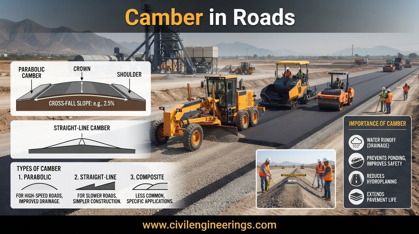
A road may look almost flat to an untrained eye, but a properly designed pavement surface is rarely horizontal. The slight transverse slope provided across the road carriageway performs an important engineering function: it directs rainwater away from the pavement before water can penetrate the surface or accumulate in wheel paths. This transverse slope is commonly known as camber in roads, also called cross slope or crossfall in many highway engineering practices.
Proper camber influences pavement durability, riding quality, drainage, skid resistance, maintenance requirements, and road safety. If the slope is too small, rainwater may remain on the pavement. If it is excessive, vehicles can experience discomfort, lateral movement, or difficulties with road alignment and access.
In this guide, we will examine the meaning of camber in roads, its purpose, types, standard values, design formula, calculation methods, construction procedures, field measurement, common defects, and practical recommendations. The discussion also explains how camber interacts with pavement type, rainfall, shoulders, superelevation, drainage systems, and modern highway design practices.
What Is Camber in Roads?
Camber in roads is the transverse slope provided to the surface of a carriageway so that rainwater flows from the pavement toward the road edges and drainage facilities.
It is normally expressed as a percentage (%) or as a ratio such as 1 in 40, 1 in 50, or 1 in 33.
For example, a camber of 2% means that the pavement surface rises or falls vertically by 2 units for every 100 horizontal units.
The basic relationship is:
Camber (%) = (Vertical rise or fall / Horizontal distance) × 100
For a road with a 2% cross slope:
Camber = 2/100 = 0.02
Therefore, over a horizontal distance of 4 m, the elevation difference is:
Elevation difference = 4 × 0.02 = 0.08 m
So, the pavement edge would differ in elevation from the reference point by approximately 80 mm, depending on the adopted cross-section.
Camber should not be confused with longitudinal gradient. Longitudinal gradient controls water movement along the road, while camber controls water movement across the pavement.
Why Is Camber Provided in Roads?
Surface Water Drainage
The primary purpose of camber is to remove rainfall from the pavement surface.
Without sufficient transverse slope, water can remain in depressions and wheel tracks. Surface water may then enter cracks, joints, pavement edges, or porous materials.
Effective highway drainage is essential because prolonged water exposure can contribute to pavement deterioration. IRC guidance also identifies transverse drainage through suitable camber as an important component of roadway drainage.
Protection of Pavement Layers
Water is one of the major causes of pavement distress.
When water infiltrates the pavement system, it can weaken granular layers and subgrade materials, accelerate stripping in susceptible bituminous mixtures, contribute to pumping in rigid pavements, and increase the likelihood of potholes and other defects.
A correctly constructed camber helps reduce the time that water remains on the pavement.
Improved Traffic Safety
Standing water can reduce tyre-pavement contact and increase the possibility of hydroplaning. Proper cross slope helps water leave the travelled way more quickly.
AASHTO-related pavement evaluation work also recognizes cross-slope and drainage paths as important considerations when identifying roadway areas that may have increased hydroplaning potential.
Reduced Maintenance
Good surface drainage reduces recurring problems such as water ponding, edge deterioration, potholes, erosion and premature pavement failures.
Camber therefore forms part of a larger pavement drainage strategy rather than functioning as an isolated geometric feature.
Better Service Life
A pavement that remains comparatively dry generally performs better than one repeatedly exposed to standing or infiltrating water.
However, camber alone cannot guarantee pavement durability. The pavement must also have appropriate materials, adequate compaction, proper drainage layers, sound shoulders, sealed joints where applicable, and adequate structural capacity.
Types of Camber in Roads
The shape of the transverse pavement profile depends on the road type, pavement material, drainage requirements and geometric design.
Straight or Plane Camber
In a straight camber, the pavement surface consists of straight slopes extending from the crown toward the edges.
For a two-lane road, the highest point is commonly located near the centerline, with each half of the carriageway falling toward its respective edge.
This arrangement is relatively simple to set out and construct.
Parabolic Camber
A parabolic camber uses a curved transverse profile rather than two simple straight lines.
The central portion may be comparatively flatter, while the slope increases toward the edges.
This arrangement can provide a smoother transition across the pavement, although construction and control are more demanding than for a simple plane slope.
Composite Camber
Composite camber combines different transverse slopes or geometric shapes across the carriageway.
It may be considered where traffic requirements, pavement width, drainage characteristics or special cross-sectional arrangements justify a more complex profile.
Two-Plane or Crowned Camber
A crowned road has a central high point, with the pavement falling toward both edges.
This is one of the most familiar arrangements on conventional two-way roads.
The crown assists drainage by directing water toward both sides of the carriageway.
Uni-Directional Crossfall
Divided roads commonly use a uni-directional crossfall on each carriageway.
Instead of having a central crown within each carriageway, the entire carriageway can slope toward one outer edge or another drainage location.
IRC guidance for divided roads recognizes uni-directional crossfall arrangements, subject to the applicable design requirements.
Typical Camber Values for Different Road Surfaces
Camber should always be selected according to the applicable road authority’s current standard rather than copied from a generic table.
As an example, Draft IRC:73-2020 provides different camber values based on surface type and rainfall conditions. Its table gives higher transverse slopes for surfaces such as earth, gravel and water-bound macadam than for high-quality bituminous or cement-concrete surfaces.
The values presented in that draft include:
| Road Surface | Low Rainfall | High Rainfall |
|---|---|---|
| High-type bituminous surfacing or cement concrete | 2.0% | 2.5% |
| Thin bituminous surfacing | 3.0% | 3.5% |
| Water-bound macadam or gravel | 3.5% | 4.0% |
| Earth road | 4.0% | 5.0% |
These figures should be treated as reference values from the cited IRC draft, not as a universal specification for every project.
The final design should follow the contract documents, governing road authority, pavement type, climatic conditions and latest applicable standard.
Factors Affecting Camber Design
Type of Pavement Surface
Smooth, dense pavement surfaces generally require less cross slope than rougher or more permeable surfaces because water can move more readily over the finished surface.
Earth and gravel roads generally require greater slopes because their surface characteristics and drainage behaviour differ from those of high-quality bituminous or concrete pavements.
Rainfall Intensity
Climate has a direct influence on drainage requirements.
Areas receiving intense or frequent rainfall may require greater attention to crossfall, drainage capacity, shoulders, side drains, kerbs, outlets and hydraulic continuity.
The engineer should consider not only annual rainfall but also rainfall intensity, storm duration and the drainage characteristics of the surrounding catchment.
Pavement Width
A wide carriageway increases the distance water may have to travel transversely before reaching a drainage edge.
For wide roads, the cross-sectional arrangement should be carefully coordinated with drainage inlets, kerbs, channels and longitudinal gradients.
Longitudinal Gradient
Camber and longitudinal gradient work together.
A road with adequate camber but poor longitudinal drainage may still experience water-related problems. Conversely, a steep longitudinal gradient does not eliminate the need for appropriate transverse slope.
Roadside Drainage
The pavement can discharge water effectively only when the receiving drainage system can handle it.
Side drains, kerbs and channels, catch basins, inlets, culverts and outlets should therefore be designed as an integrated system.
Traffic and Operating Conditions
Camber also influences vehicle behaviour.
An excessively steep cross slope can create uncomfortable lateral forces and may become particularly important for motorcycles, cyclists, slow-moving vehicles and vehicles transitioning between different cross-sectional conditions.
Camber Formula and Numerical Example
The basic formula is:
Camber (%) = (Difference in elevation / Horizontal distance) × 100
Alternatively:
Difference in elevation = Horizontal distance × Camber
Example
Suppose a two-lane pavement has a transverse half-width of 3.5 m and the specified camber is 2.5%.
The required elevation difference from the crown to the pavement edge is:
Rise/Fall = 3.5 × 0.025
Rise/Fall = 0.0875 m
Therefore:
Rise/Fall = 87.5 mm
If the crown is at an elevation of 100.000 m, the theoretical pavement-edge elevation would be approximately:
100.000 − 0.0875 = 99.9125 m
This simplified calculation assumes a straight plane slope and should be adjusted when the pavement cross-section uses a different geometric profile.
Camber vs Superelevation
Camber & superelevation are related but serve different purposes.
Superelevation is introduced on horizontal curves to help counteract the lateral acceleration experienced by vehicles.
On a straight crowned road, water generally flows away from the center toward both edges.
On a superelevated curve, the pavement may slope predominantly in one direction. The crossfall arrangement must therefore be transitioned carefully between normal camber and the required superelevation.
An engineer should never simply apply normal camber to a horizontal curve without checking the geometric design requirements.
Camber and Road Drainage Design
Camber is only one part of an effective highway drainage system.
A properly designed drainage arrangement may include:
- Pavement cross slope
- Longitudinal gradient
- Shoulders
- Side drains
- Kerb and channel systems
- Catch pits
- Drainage inlets
- Culverts
- Median drainage
- Cross-drainage structures
- Outfalls
- Erosion protection
IRC material on highway drainage emphasizes the need to remove water from the pavement and prevent water-related pavement deterioration.
ICE highway engineering guidance similarly treats geometric design and drainage design as important components of effective highway design.


How to Construct Camber in Roads
Establish the Design Levels
Before construction, the survey team should establish the required centerline, edge levels, formation levels and pavement elevations.
The setting-out data should come directly from the approved design drawings.
Prepare the Subgrade
The subgrade must be shaped to the specified cross-sectional profile.
Proper moisture conditioning and compaction are essential. If the underlying layer has an incorrect profile, subsequent pavement layers may not fully correct the defect.
Construct Subbase and Base Layers
Each pavement layer should maintain the designed transverse profile.
The construction team should check both thickness and crossfall. A layer that appears visually correct may still have local deviations that become more difficult to correct at the finished surface.
Place the Surface Course
The final bituminous or concrete surface should achieve the specified camber without abrupt deviations.
For asphalt pavement, paving equipment, screed control, stringlines, sensors or 3D machine-control systems may be used depending on the project.
For concrete pavement, formwork, slipform pavers and level-control systems can establish the designed cross profile.
Verify the Finished Surface
After construction, survey levels should be checked at representative chainages and critical locations.
Straightedges, digital levels, total stations, GNSS equipment and specialized pavement profilers can be used depending on project requirements.
Field Measurement of Camber
Camber can be checked by measuring elevations at known transverse offsets.
The basic procedure is:
- Select the chainage or test location.
- Establish the pavement centerline or reference point.
- Measure the elevation at the center or crown.
- Measure the elevation at the pavement edge.
- Determine the horizontal distance.
- Calculate the cross slope.
- Compare the measured result with the approved tolerance.
For example, if the elevation difference is 70 mm over 3.5 m:
Camber = (0.070 / 3.5) × 100
Camber = 2.0%
The engineer should also inspect the pavement visually for local depressions. A pavement can have an acceptable average slope while still containing isolated low points where water accumulates.
IRC material on highway asset assessment includes camber among the parameters used for evaluating drainage-related highway conditions. (irc.nic.in)
Common Problems Caused by Incorrect Camber
Insufficient Camber
When the cross slope is too small, water may remain on the pavement.
Typical consequences include:
- Water ponding
- Reduced skid resistance
- Increased hydroplaning risk
- Moisture infiltration
- Accelerated pavement deterioration
- Edge and shoulder damage
Excessive Camber
Too much cross slope can also create problems.
Potential consequences include:
- Uncomfortable vehicle movement
- Increased lateral force
- Difficulties for cyclists and motorcycles
- Uneven pavement wear
- Problems at intersections and access points
- Complications when transitioning into curves
Irregular Camber
In practice, irregularity is often more problematic than a small uniform deviation.
A pavement with alternating high and low areas can trap water even when the calculated average cross slope appears satisfactory.
Poor Shoulder Connection
A correctly sloped carriageway can still perform poorly if the shoulder is too high, too low or incorrectly compacted.
Water leaving the pavement should have a clear route into the drainage system.
Camber on Shoulders
Shoulders require their own crossfall considerations.
The shoulder should generally allow water to continue moving away from the carriageway rather than creating a secondary water trap.
Draft IRC:73-2020 indicates that an earthen shoulder should have a crossfall steeper than the pavement camber, subject to specified minimum requirements. It also notes that paved shoulders should be designed according to the surface type.
The actual project design should always control over generalized rules.
Camber on Urban Roads
Urban roads require additional attention because kerbs, footpaths, medians, driveways, utility covers and stormwater inlets constrain the available drainage path.
A simple crowned rural-road profile may not be appropriate for every urban street.
Engineers may use:
- One-way crossfall
- Kerb-and-channel drainage
- Central drainage arrangements
- Side-entry inlets
- Grated inlets
- Continuous channels
- Dedicated stormwater systems
The pavement profile must coordinate with finished floor levels, property accesses and pedestrian facilities.
Camber on Bridges and Structures
Bridge decks require particularly careful surface drainage.
Water should not be allowed to remain on the deck or discharge onto sensitive structural components.
IRC guidance for grade separators notes that transverse drainage should be provided through suitable camber, with longitudinal drainage supported by appropriate gradient and drainage fixtures.
Bridge deck drainage therefore requires coordination between road geometry, waterproofing, kerbs, scuppers, outlets and structural detailing.
Camber Design on Divided Highways
Divided highways introduce additional cross-sectional options.
Each carriageway may use a uni-directional crossfall rather than a central crown.
The engineer should coordinate:
- Median drainage
- Outer shoulder drainage
- Pavement crossfall
- Superelevation
- Kerbs
- Drainage inlets
- Longitudinal gradients
- Emergency stopping areas
On high-speed facilities, small changes in pavement profile can influence drainage paths and operational safety, so digital terrain models and detailed cross-section checks are increasingly useful.
Practical Recommendations for Civil Engineering Students
Students should understand camber as an interaction between road geometry and drainage, rather than memorizing isolated percentages.
When solving examination or design problems:
- Identify the pavement surface.
- Determine the specified camber.
- Convert the percentage into a decimal.
- Multiply it by the horizontal width.
- Calculate the elevation difference.
- Draw a clear cross-section.
- Check whether the result is physically reasonable.
Students should also learn the distinction between camber, crossfall, gradient and superelevation.
A simple hand-drawn road cross-section is often the fastest way to understand the concept.
Practical Recommendations for Highway Engineers
Engineers should verify camber at the design, construction and maintenance stages.
Do not rely solely on design drawings. Field conditions can alter the final profile through settlement, resurfacing, utility work, patching and construction tolerances.
During inspections, look specifically for:
- Wheel-path rutting
- Local depressions
- Shoulder buildup
- Edge drop-off
- Blocked drainage inlets
- Settlement
- Ponding after rainfall
- Incorrect resurfacing levels
Digital survey equipment and pavement profilers can significantly improve the reliability of cross-slope assessment.
ICE emphasizes that highway design should integrate geometric design, pavement, drainage, site investigation and other engineering disciplines rather than treating each component independently.
Practical Recommendations for Contractors
Contractors should treat crossfall as a controlled construction requirement, not simply a visual feature.
Before paving:
- Check survey control points.
- Verify formation levels.
- Confirm layer thicknesses.
- Check drainage structures.
- Inspect the prepared surface.
During paving:
- Monitor screed or paver levels.
- Check transverse profile at regular intervals.
- Avoid excessive manual correction.
- Maintain proper compaction procedures.
After paving:
- Carry out level checks.
- Inspect for ponding.
- Verify shoulder transitions.
- Confirm drainage paths.
- Rectify unacceptable depressions before opening the road.
A small construction error repeated over a long highway section can become a significant drainage problem.
IRC, AASHTO and ICE Guidance
Camber requirements should never be selected solely from a generic internet table.
In India, engineers commonly consult relevant Indian Roads Congress (IRC) standards and guidelines along with applicable MoRTH specifications and project documents. IRC maintains technical committees covering highway design, flexible and rigid pavements, drainage, rural roads, maintenance and road safety. (irc.nic.in)
IRC’s published material includes guidance relevant to road surface crossfall and drainage. The cited Draft IRC:73-2020 provides a useful example of how camber values can vary according to pavement surface and rainfall conditions. (irc.nic.in)
For projects following American practice, engineers should consult the applicable AASHTO standards and project-specific agency requirements. AASHTO-related pavement tools and research also demonstrate the importance of cross-slope and drainage-path evaluation.
For UK and related international practice, ICE resources provide broader highway engineering guidance covering geometric design, drainage, pavement engineering and highway development. (Institution of Civil Engineers (ICE))
The key principle is simple: use the latest applicable standard specified by the road authority and contract documents. Standards are periodically revised, so old textbook values should not automatically be treated as current design requirements.
Camber in Roads: Key Engineering Principles
A sound camber design follows several fundamental principles:
- Provide enough slope to remove surface water efficiently.
- Avoid unnecessarily steep crossfall.
- Coordinate camber with longitudinal gradient.
- Match shoulder levels with the pavement drainage path.
- Consider rainfall and drainage capacity.
- Account for pavement surface type.
- Coordinate camber with superelevation on curves.
- Check the finished surface rather than relying only on drawings.
- Prevent local depressions.
- Maintain drainage facilities throughout the pavement life.
The most important lesson is that camber is not merely a geometric percentage. It is part of the complete pavement-water management system.
Advantages of Proper Camber in Roads
Properly designed and constructed camber provides several benefits:
- Faster removal of rainwater
- Reduced surface ponding
- Improved wet-weather safety
- Lower moisture infiltration
- Better pavement durability
- Reduced drainage-related maintenance
- Improved riding conditions
- Better protection of pavement edges
- More reliable highway drainage performance
These benefits become especially important on heavily trafficked roads and in regions exposed to intense rainfall.
Limitations and Design Considerations
Camber should not be treated as a universal solution to pavement drainage problems.
A road can have the correct cross slope and still experience waterlogging because of blocked drains, inadequate longitudinal gradient, settlement, rutting, poor shoulder construction or insufficient drainage capacity.
Similarly, increasing camber beyond the design requirement is not necessarily beneficial.
The correct approach is to consider the entire pavement cross-section, hydraulic path and geometric design together.
Frequently Asked Questions About Camber in Roads
What is camber in roads?
Camber in roads is the transverse slope provided across the pavement surface to facilitate drainage of rainwater from the carriageway toward the road edges or designated drainage systems.
Why is camber provided on roads?
The main purpose is to remove surface water quickly. Proper camber helps reduce ponding, improve wet-weather safety and protect pavement layers from prolonged moisture exposure.
What is the formula for camber?
The basic formula is:
Camber (%) = (Difference in elevation / Horizontal distance) × 100
The formula can be rearranged to determine the required elevation difference.
What is the difference between camber and superelevation?
Camber primarily provides transverse drainage on normal road sections. Superelevation is used mainly on horizontal curves to manage vehicle lateral forces and is designed as part of highway geometric alignment.
What is a typical camber for bituminous roads?
The value depends on the applicable standard, pavement surface, climate and project requirements. For example, Draft IRC:73-2020 lists 2.0% for certain high-type bituminous surfaces under low-rainfall conditions and 2.5% under high-rainfall conditions.
Can excessive camber damage a road?
Excessive crossfall can create undesirable vehicle lateral movement, discomfort and operational problems. Therefore, camber should be optimized rather than simply maximized.
How is camber measured at a construction site?
Engineers can measure pavement elevations at the crown and edge using a level, total station, GNSS equipment or other approved surveying equipment. The elevation difference is then divided by the horizontal distance to calculate the actual cross slope.
Does camber apply to concrete roads?
Yes. Concrete pavements also require appropriate transverse slope for surface drainage. The exact value depends on the governing design standard, pavement configuration and drainage arrangement.
Should road shoulders have the same camber as the pavement?
Not necessarily. Shoulder crossfall depends on the shoulder surface and project standard. Some standards require shoulders, particularly earthen shoulders, to have a steeper slope than the pavement so that water continues away from the carriageway.
Is camber enough to provide road drainage?
No. Camber works together with longitudinal gradient, shoulders, kerbs, drains, inlets, culverts and outfalls. A complete drainage system is necessary for reliable long-term performance.
Conclusion
Camber in roads is a small geometric feature with a major influence on pavement performance, drainage and road safety. By creating an appropriate transverse slope, engineers provide a controlled path for rainwater to leave the pavement surface rather than allowing it to accumulate in wheel paths or infiltrate pavement layers.
Good camber design requires more than selecting a percentage from a table. Pavement type, rainfall, road width, longitudinal gradient, shoulder configuration, drainage facilities, traffic conditions and horizontal alignment all need consideration. Construction quality is equally important because an accurately designed cross-section can still fail when poor grading, settlement, rutting or irregular paving creates local depressions.
