
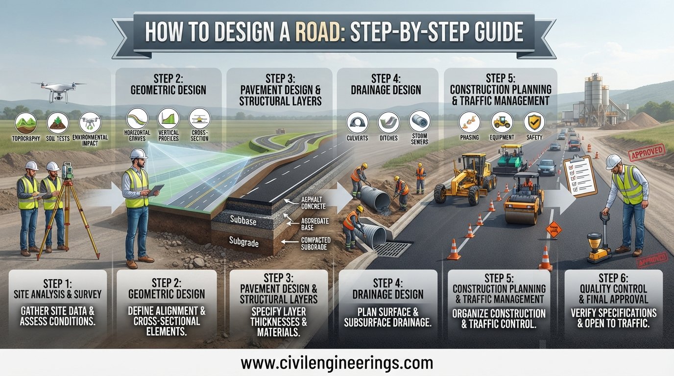
Designing a road is much more than drawing a centerline between two locations. A successful roadway must safely accommodate traffic, respond to terrain and soil conditions, drain stormwater, support pavement loads, control construction costs, and remain maintainable for decades. That is why How to Design a Road is a fundamental question in highway engineering, transportation engineering, and civil infrastructure development.
Road design combines planning, traffic studies, surveying, geotechnical investigation, geometric design, pavement engineering, drainage, road safety, and construction detailing. The horizontal alignment, vertical profile, and cross-section must work together as one three-dimensional system.
This guide explains the complete road design process from initial planning and route selection to final drawings, pavement design, drainage, safety checks, and construction documentation. It also includes practical formulas, engineering principles, examples, and recommendations for students, engineers, consultants, and contractors.
What Does Road Design Mean?
Road design is the engineering process of determining the location, geometry, dimensions, structural composition, drainage arrangements, safety features, and construction requirements of a road.
In practical highway engineering, road design answers questions such as:
- Where should the road be located?
- How wide should the carriageway be?
- What design speed should be adopted?
- How much traffic must the road carry?
- What horizontal curve radius is appropriate?
- How steep can the road gradient be?
- What pavement thickness is required?
- How will rainwater leave the pavement?
- Where should intersections, pedestrian facilities, signs, and barriers be located?
- How much earthwork will construction require?
Geometric design generally consists of three closely connected components: horizontal alignment, vertical alignment, and cross-section. Together, they create the three-dimensional form of the roadway.


Step 1: Define the Road Function and Design Requirements
Before opening AutoCAD Civil 3D or another road design program, establish what the road needs to accomplish.
A residential street, rural collector, urban arterial, expressway, and major intercity highway cannot use the same design approach. Functional classification influences design speed, lane configuration, access control, intersections, pedestrian facilities, and expected traffic.
Determine the Road Classification
Typical classifications include:
- Local roads
- Collector roads
- Arterial roads
- Rural highways
- Urban roads
- Divided highways
- Expressways
- Freeways
The road’s role within the transportation network should be clear before geometric parameters are selected. Modern guidance also recognizes that context matters. AASHTO’s Green Book, for example, combines traditional functional classification with context classifications such as rural, suburban, urban, and urban-core environments.
Establish the Design Controls
Important design controls include:
- Design speed
- Traffic volume
- Design vehicle
- Terrain
- Road classification
- Right-of-way availability
- Environmental constraints
- Existing utilities
- Pedestrian and cyclist requirements
- Flood risk
- Geotechnical conditions
- Required level of service
- Future traffic growth
A common mistake is selecting a design speed first and attempting to force every other parameter around it. Good design considers the complete road context and the expectations of road users.
Step 2: Carry Out Traffic Studies
Traffic is one of the most important inputs in road design.
The engineer needs to understand both present and future traffic demand. A road that performs well today may become congested if its design ignores future growth.
Collect Traffic Data
Typical investigations include:
- Average daily traffic
- Peak-hour traffic
- Directional distribution
- Vehicle classification
- Heavy commercial vehicles
- Turning movements
- Pedestrian movements
- Bicycle demand
- Public transport demand
- Seasonal traffic variation
For major projects, traffic forecasting may extend over the selected design life.
A simplified future traffic calculation can be expressed as:
Where:
- = estimated future traffic
- = present traffic
- = annual growth rate
- = number of years
For example, if current traffic is 8,000 vehicles/day, annual growth is 4%, and the planning period is 15 years:
This gives approximately 14,411 vehicles/day.
The actual design should use the traffic methodology required by the relevant highway authority rather than relying only on this simplified equation.
Step 3: Conduct Reconnaissance and Route Surveys
Once the design requirements are understood, investigate the available corridor.
Route selection can have a greater effect on project cost than many later design decisions. A poor alignment can create excessive excavation, embankment, retaining structures, drainage problems, land acquisition, and environmental impacts.
Perform Desktop and Field Investigations
Initial studies may include:
- Topographic maps
- Satellite imagery
- Existing road networks
- Land-use maps
- Geological information
- Hydrological data
- Flood maps
- Property boundaries
- Utility records
- Environmental constraints
- Existing bridges and culverts
Field reconnaissance then verifies actual conditions.
The conventional location survey process moves from desk study and route identification through reconnaissance, alternative alignment assessment, preliminary centerline selection, final alignment, and construction plans.
Select the Preferred Corridor
A good route should balance:
- Safety
- Travel efficiency
- Construction cost
- Land acquisition
- Earthwork
- Drainage
- Environmental impact
- Social impact
- Future development
- Maintenance requirements
The shortest route is not necessarily the best route.
Step 4: Carry Out Topographic and Geotechnical Surveys
Accurate survey information forms the foundation of road design.
Topographic Survey
The survey should capture:
- Existing ground levels
- Contours
- Buildings
- Trees
- Drainage channels
- Roads
- Utility poles
- Culverts
- Bridges
- Property boundaries
- Watercourses
- Existing pavement
- Other physical obstacles
Modern projects may combine total stations, GNSS, drones, LiDAR, and conventional surveying.
Geotechnical Investigation
The pavement ultimately transfers traffic loads into the soil. Therefore, soil behavior must be understood before pavement thickness and earthwork treatments are finalized.
Typical tests may include:
- Grain-size analysis
- Atterberg limits
- Compaction testing
- CBR testing
- Plate load testing where appropriate
- Soil classification
- Groundwater investigation
- Field density testing
Weak subgrade soils may require stabilization, replacement, geosynthetics, improved drainage, or other treatment.
ICE guidance emphasizes that effective highway design depends on understanding material properties, design loading, existing ground conditions, and environmental interaction.
Step 5: Design the Horizontal Alignment
Horizontal alignment determines where the road travels when viewed from above.
It normally consists of tangents, circular curves, and transition curves.
Determine Horizontal Curve Radius
A simplified relationship between speed, radius, superelevation, and side friction is:
Where:
- = curve radius in metres
- = speed in km/h
- = superelevation expressed as a decimal
- = side-friction factor
For illustration, suppose:
- km/h
Then:
This is only an illustrative calculation. The controlling minimum radius must come from the applicable design standard, road context, terrain, and adopted design criteria.
Check Sight Distance
A horizontal curve may have sufficient radius but still provide inadequate visibility if vegetation, rock cuts, buildings, barriers, or other objects obstruct the driver’s view.
Sight distance should therefore be checked independently.
Important sight-distance categories include:
- Stopping sight distance
- Passing/overtaking sight distance
- Decision sight distance
- Intersection sight distance
Sight distance is a fundamental safety consideration in geometric design.
Provide Superelevation
On a horizontal curve, the pavement is tilted to help counteract lateral acceleration.
A simplified concept is:
The exact allowable superelevation and friction values depend on the governing standard.
Superelevation should transition gradually. Abrupt changes can create uncomfortable vehicle behavior and drainage problems.
Step 6: Design the Vertical Alignment
The vertical alignment controls the road’s elevation and grades when viewed longitudinally.
It consists mainly of:
- Straight grade sections
- Crest vertical curves
- Sag vertical curves


Select Suitable Gradients
Road grades should consider:
- Design speed
- Terrain
- Heavy vehicles
- Drainage
- Accessibility
- Pedestrian movement
- Road classification
- Winter or adverse weather conditions where applicable
Steep grades may be unavoidable in mountainous terrain, but they can reduce heavy-vehicle performance and affect safety.
Design Vertical Curves
Vertical curves provide a smooth transition between different grades.
For example, a crest curve may need sufficient length to provide the required stopping sight distance. A sag curve must also provide adequate visibility and acceptable comfort while considering headlight visibility where relevant.
A useful conceptual relationship is:
Where represents the algebraic difference between entering and exiting grades.
The selected vertical curve length should then be determined using the appropriate standard and sight-distance requirements.
Step 7: Design the Road Cross-Section
The cross-section defines the road’s width and lateral features.
Typical components include:
- Traffic lanes
- Median
- Shoulders
- Kerbs
- Footways
- Cycle facilities
- Verge
- Side drains
- Side slopes
- Clear zones
- Roadside barriers
Cross-sections also connect the proposed roadway to existing ground and provide the information needed for earthwork quantity calculations. (ScienceDirect)


Determine Lane and Shoulder Widths
Width depends on:
- Road classification
- Traffic demand
- Design vehicle
- Speed
- Urban or rural context
- Available right-of-way
- Safety requirements
- Pedestrian and cyclist needs
Do not select dimensions from a generic online table without checking the governing road authority’s standard.
Provide Cross Slope or Camber
Cross slope helps remove water from the pavement.
A simplified expression is:
Where:
- = cross slope
- = elevation difference
- = horizontal distance
For example, a 2% cross slope means a 2-unit elevation change for every 100 horizontal units.
The selected crossfall depends on pavement type, surface characteristics, climate, drainage requirements, and applicable standards.
Step 8: Design the Pavement Structure
A road is not simply a compacted earth surface with asphalt on top. The pavement is a layered structural system.
A typical flexible pavement may include:
- Wearing/surface course
- Binder course
- Base course
- Subbase
- Compacted subgrade
The exact layer arrangement varies according to pavement type, traffic, climate, materials, and design method.
Flexible and Rigid Pavement
Flexible pavement generally uses asphaltic surfacing over granular or stabilized layers.
Rigid pavement uses a concrete slab that distributes wheel loads differently.
Pavement design should consider:
- Traffic loading
- Axle loads
- Subgrade strength
- Material properties
- Climate
- Drainage
- Reliability
- Design life
- Maintenance strategy
The final thickness should come from the selected pavement design methodology rather than a universal thickness rule.
Step 9: Design Drainage
Water is one of the greatest threats to pavement performance.
Poor drainage can cause:
- Subgrade weakening
- Potholes
- Rutting
- Edge failures
- Erosion
- Shoulder deterioration
- Slope instability
- Flooding
Drainage should therefore be designed at the same time as geometric alignment and pavement.
Surface Drainage
Surface drainage may include:
- Road camber
- Kerb and gutter
- Side drains
- Chutes
- Inlets
- Catch basins
- Outfalls
Cross-Drainage
Where water crosses the roadway, engineers may use:
- Pipe culverts
- Box culverts
- Slab culverts
- Bridges
- Causeways where appropriate
Hydraulic calculations should account for catchment characteristics, rainfall, runoff, inlet and outlet conditions, permissible velocities, flood levels, and downstream impacts.
ICE identifies drainage as a fundamental component of highway design, alongside geometric design and site investigation. (Institution of Civil Engineers (ICE))
Step 10: Design Intersections and Roadside Features
A road does not operate independently. Junctions often control safety and capacity.
Possible intersection treatments include:
- Priority junctions
- Signalized intersections
- Roundabouts
- Grade-separated interchanges
- Channelized intersections
Design should consider turning paths, visibility, pedestrian crossings, bicycle movements, traffic control, queues, storage lengths, and access management.
Roadside elements also deserve detailed attention.
These may include:
- Guardrails
- Crash cushions
- Delineators
- Signs
- Pavement markings
- Lighting
- Emergency stopping areas
- Clear zones
- Safety barriers
Modern safety thinking increasingly focuses on preventing fatal and serious outcomes rather than merely moving vehicles efficiently. ICE’s recent discussion of safer junction design highlights this broader Safe System approach. (Institution of Civil Engineers (ICE))
Step 11: Calculate Earthwork Quantities
Once the alignment, profile, and cross-section are established, calculate excavation and embankment quantities.
Typical outputs include:
- Cut volume
- Fill volume
- Borrow requirements
- Suitable excavated material
- Unsuitable material
- Haul quantities
- Disposal requirements
For regularly spaced cross-sections, one common approximation is the average end-area method:
Where:
- = first cross-sectional area
- = second cross-sectional area
- = distance between sections
For greater accuracy, digital terrain models and corridor models can calculate volumes across numerous sections.
Earthwork optimization is valuable because excessive cut-and-fill can significantly increase construction cost.
Step 12: Prepare Road Design Drawings
A professional road design package should communicate the design clearly enough for construction, checking, measurement, and approval.
Typical drawings include:
- Key plan
- General arrangement
- Horizontal alignment plan
- Longitudinal profile
- Typical cross-sections
- Detailed cross-sections
- Pavement details
- Drainage drawings
- Culvert details
- Intersection layouts
- Road furniture
- Signage and marking plans
- Utility relocation drawings
- Earthwork drawings
- Construction details
The relationship between plan, profile, and cross-section must be checked carefully. A mathematically correct horizontal alignment can still produce an unsafe or impractical road when combined poorly with the vertical profile.
Step 13: Use Road Design Software Correctly
Software can dramatically improve productivity, but it does not replace engineering judgment.
Common tools include:
- AutoCAD Civil 3D
- OpenRoads Designer
- MX
- GIS platforms
- Hydraulic modeling software
- Pavement design software
- Traffic simulation software
- Quantity and cost-estimation tools
A typical Civil 3D workflow may include:
Survey data → Existing surface → Alignment → Profile → Assembly → Corridor → Sample lines → Quantities → Plan production
The software should automate calculations and drawing production while the engineer remains responsible for design decisions.
Step 14: Perform QA/QC and Safety Checks
Before issuing drawings, perform an independent design review.
Geometric Checks
Verify:
- Design speed
- Curve radii
- Superelevation
- Transition lengths
- Grades
- Vertical curves
- Sight distance
- Lane widths
- Shoulder widths
- Crossfall
- Intersection geometry
Drainage Checks
Verify:
- Catchment assumptions
- Drain capacity
- Culvert capacity
- Outfall conditions
- Flood levels
- Erosion protection
- Longitudinal drainage
Constructability Checks
Ask:
- Can contractors actually build the proposed geometry?
- Are temporary works feasible?
- Are utilities conflicting with drainage?
- Are retaining structures required?
- Is sufficient right-of-way available?
- Can traffic be maintained during construction?
- Are material sources practical?
A professional review should consider safety, constructability, environmental impacts, and lifecycle cost—not just whether CAD drawings look correct.
Road Design Standards: IRC, AASHTO and ICE Guidance
Road design should always follow the standard adopted by the relevant client, jurisdiction, or highway authority.
IRC
For projects in India and projects influenced by Indian practice, engineers should consult the applicable Indian Roads Congress documents. IRC has published/revised geometric-design documents including IRC:73-2023, Geometric Design Standards for Non-Urban Roads. (IRINN)
The IRC publication system also covers road geometric and design features, pavement design, maintenance, roadside facilities, and other highway topics. (IRINN)
AASHTO
For projects following U.S. practice or AASHTO-based criteria, the AASHTO Green Book is a major reference for geometric design. Its seventh edition provides a more flexible, performance-based framework and considers both roadway function and context.
ICE and UK Practice
ICE provides highway engineering guidance and points practitioners toward established procedures, including geometric design, site investigation, foundation design, drainage, pavement engineering, and highway management. UK projects also rely on the Design Manual for Roads and Bridges and associated highway specifications.
These standards should not be mixed casually. A road should have a clearly identified governing design basis, with project-specific departures or adaptations documented and approved where required.
Practical Recommendations for Students, Engineers and Contractors
For Civil Engineering Students
Start with the fundamentals before learning software.
Learn:
- Highway classification
- Traffic engineering
- Surveying
- Horizontal curves
- Vertical curves
- Superelevation
- Sight distance
- Pavement design
- Drainage
- Earthwork calculations
Then reproduce a small road project in Civil 3D or similar software.
For Highway Engineers and Consultants
Keep a documented design basis from the beginning.
Record:
- Design speed
- Design vehicle
- Traffic assumptions
- Survey accuracy
- Geotechnical parameters
- Design standards
- Pavement criteria
- Drainage criteria
- Design exceptions
- Safety decisions
This makes technical review substantially easier.
For Site Engineers and Contractors
Do not construct from geometry alone.
Check:
- Centerline coordinates
- Benchmarks
- Formation levels
- Crossfall
- Superelevation
- Layer thickness
- Compaction
- Drainage levels
- Material specifications
- Setting-out data
Small errors in formation level or crossfall can create significant drainage and pavement problems later.
For Government and Infrastructure Agencies
Evaluate the road over its entire lifecycle.
The lowest initial construction cost is not always the lowest overall cost. Consider:
- Construction
- Routine maintenance
- Periodic rehabilitation
- Safety
- Drainage
- Traffic delay
- Climate resilience
- Future widening
- Asset management
Climate resilience is increasingly important because extreme weather can accelerate pavement deterioration and disrupt highway operations.
Common Road Design Mistakes to Avoid
Several mistakes appear repeatedly in poorly coordinated road projects.
1. Designing before understanding the terrain:
This often produces excessive earthwork and unnecessary structures.
2. Treating drainage as an afterthought:
Water should influence alignment, profile, pavement, and roadside design from the beginning.
3. Using unsuitable design speeds:
Design speed should reflect road function, context, terrain, and user expectations.
4. Checking plan and profile separately:
Road geometry must be evaluated as a three-dimensional system.
5. Ignoring heavy vehicles:
Trucks can strongly influence gradients, pavement loading, climbing lanes, and intersection performance.
6. Copying standard dimensions without context:
Tables are useful, but they cannot replace engineering judgment.
7. Failing to coordinate utilities:
A beautiful drainage design is useless if an existing major utility occupies the proposed alignment.
8. Ignoring construction methodology:
A theoretically sound design may become expensive or unsafe if it cannot be constructed efficiently.
Frequently Asked Questions About How to Design a Road
1. What are the main steps in road design?
The main steps include project definition, traffic studies, route selection, surveying, geotechnical investigation, horizontal alignment, vertical alignment, cross-section design, pavement design, drainage, intersections, safety features, earthwork calculations, drawings, and QA/QC.
2. What is the most important part of road design?
There is no single most important component. A successful road requires coordination between traffic demand, geometric design, pavement, drainage, geotechnical conditions, safety, constructability, and lifecycle requirements.
3. How is road design speed selected?
Design speed depends on road classification, terrain, traffic function, surrounding development, user expectations, safety objectives, and the governing design standard.
4. What software is used to design roads?
Common software includes Civil 3D, OpenRoads Designer, MX, GIS platforms, traffic-analysis tools, hydraulic modeling programs, and pavement design software.
5. What is horizontal alignment in road design?
Horizontal alignment represents the road’s path in plan view. It typically consists of tangents, circular curves, and transition curves.
6. What is vertical alignment?
Vertical alignment represents the road’s elevation along its length. It consists of grades and vertical curves, including crest and sag curves.
7. Why is drainage important in road design?
Drainage protects pavement and earthworks from water damage. Effective drainage reduces saturation, erosion, potholes, edge failures, and premature pavement deterioration.
8. Which standards should engineers use for road design?
Use the standards specified by the project authority. Depending on location, these may include IRC, AASHTO, DMRB, Austroads, national standards, or other approved highway design manuals. Current guidance should always be verified before final design.
9. Can road design be completed entirely using software?
No. Software can model geometry, surfaces, corridors, quantities, and drawings, but engineers must establish design criteria, interpret site conditions, evaluate safety, and make professional decisions.
10. How can road design costs be reduced?
The best opportunities usually come from early decisions: selecting a practical corridor, balancing cut and fill, optimizing structures, using suitable local materials, coordinating utilities, designing effective drainage, and considering future maintenance.
Conclusion
Learning How to Design a Road requires more than memorizing curve formulas or learning CAD commands. Professional road design is an integrated engineering process in which traffic, terrain, geometry, pavement, drainage, safety, environment, construction, and future maintenance influence one another.
The most reliable workflow begins with defining the road function and design controls. Engineers then investigate traffic, survey the corridor, study soil and drainage conditions, develop the horizontal and vertical alignment, design the cross-section, select the pavement structure, calculate earthwork, and prepare coordinated construction drawings. Every stage should be checked against the governing standards and practical site conditions.
For students, the best approach is to master the engineering principles first and then apply them through real or simulated projects. For practicing engineers and contractors, careful coordination between design documents and field conditions is equally important.
Ultimately, a well-designed road should be safe, functional, economical, constructible, durable, accessible, and adaptable. That is the real objective of modern road engineering—not simply producing a line on a drawing, but creating infrastructure that performs reliably throughout its service life.
