
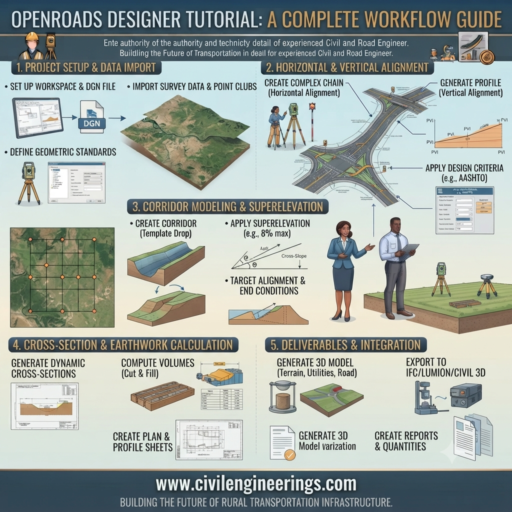
Introduction
Modern highway infrastructure demands precision, efficiency, and compliance with engineering standards. Traditional drafting methods are no longer sufficient for today’s complex transportation projects. Engineers now rely on advanced Building Information Modeling (BIM) software to design safer, smarter, and more sustainable roads.
This Open Roads Designer Tutorial is designed for civil engineering students, highway engineers, transportation consultants, contractors, and researchers who want to master one of the industry’s leading roadway design platforms. Whether you are creating a rural highway, an urban street, or a multi-lane expressway, OpenRoads Designer provides powerful tools for terrain modeling, corridor creation, drainage analysis, earthwork calculations, and detailed construction documentation.
Throughout this guide, you’ll learn the complete workflow—from setting up a project to generating final construction drawings—using practical engineering concepts and real-world design practices. By the end, you’ll understand not only how to use the software but also why each step matters in professional highway engineering.
Table of Contents
- Introduction
- What is OpenRoads Designer?
- Why Civil Engineers Use OpenRoads Designer
- System Requirements
- Installing OpenRoads Designer
- Understanding the User Interface
- Creating Your First Highway Project
- Importing Survey Data
- Digital Terrain Model (DTM)
- Horizontal Alignment Design
- Vertical Alignment Design
- Corridor Modeling
- Superelevation Design
- Cross Sections
- Earthwork Calculations
- Drainage Design Basics
- Quantity Estimation
- Engineering Calculations
- Quality Control Procedures
- Engineering Standards
- Best Practices
- Common Mistakes
- Frequently Asked Questions
- Conclusion
What is OpenRoads Designer?
Overview
OpenRoads Designer (ORD) is Bentley Systems’ comprehensive roadway design software used for planning, designing, analyzing, and documenting transportation infrastructure. It combines intelligent 3D modeling, civil engineering workflows, and BIM technology into a single platform.
Unlike traditional CAD software that focuses mainly on drafting, OpenRoads Designer creates intelligent engineering models where every element—such as alignments, profiles, corridors, and drainage systems—is interconnected. When one component changes, related elements update automatically, reducing manual revisions and improving design accuracy.
Industries Using OpenRoads Designer
- Highway Engineering
- Transportation Engineering
- Municipal Infrastructure
- Airport Design
- Railway Engineering
- Urban Development
- Land Development
- Bridge Approach Design
Key Features
The software offers numerous features that streamline transportation design:
- Intelligent 3D roadway modeling
- Corridor modeling
- Survey data processing
- Terrain generation
- Drainage network design
- Earthwork analysis
- Quantity calculations
- Automated cross sections
- Profile generation
- BIM integration
- Construction documentation
- Clash detection
- Visualization and rendering
Typical Design Workflow
Survey Data
      │
      ▼
Terrain Model (DTM)
      │
      ▼
Horizontal Alignment
      │
      ▼
Vertical Alignment
      │
      ▼
Template Creation
      │
      ▼
Corridor Modeling
      │
      ▼
Cross Sections
      │
      ▼
Earthwork Analysis
      │
      ▼
Construction Drawings
This workflow reflects the sequence commonly followed in professional transportation design projects.
Why Civil Engineers Use OpenRoads Designer
Highway projects involve thousands of design elements that must work together seamlessly. OpenRoads Designer simplifies this complexity by integrating survey, geometric design, terrain modeling, drainage, and documentation within one environment.
Major Benefits
1. Improved Design Accuracy
Dynamic modeling minimizes drafting errors and maintains consistency throughout the project lifecycle.
2. Faster Project Delivery
Automated updates reduce repetitive work, allowing engineers to focus on design decisions instead of manual revisions.
3. Better Collaboration
Different engineering disciplines can work on the same project model while maintaining data integrity.
4. Enhanced Visualization
Three-dimensional models help engineers, clients, and stakeholders understand the project before construction begins.
5. Reduced Construction Risk
Accurate digital models improve quantity estimation, identify conflicts early, and reduce costly field changes.
Applications in Highway Engineering
A professional highway engineer may use OpenRoads Designer for:
- National highways
- Motorways
- Urban roads
- Rural roads
- Interchanges
- Flyovers
- Roundabouts
- Service roads
- Bridge approaches
- Drainage systems
- Utility coordination
- Road widening projects
System Requirements for OpenRoads Designer
Before installing the software, ensure your workstation meets the recommended specifications.
| Component | Recommended Specification |
|---|---|
| Operating System | Windows 10 or Windows 11 (64-bit) |
| Processor | Intel Core i7 / AMD Ryzen 7 or higher |
| RAM | 32 GB or more |
| Graphics Card | Dedicated GPU with DirectX support |
| Storage | SSD with at least 50 GB free space |
| Display | Full HD or higher |
| Internet | Required for licensing and updates |
For large corridor or BIM projects, higher hardware specifications significantly improve performance.
Installing OpenRoads Designer
Installing the software correctly is the first step toward an efficient design workflow.
Step 1
Download the installation package from Bentley Systems using your licensed account.
Step 2
Install the Bentley Connection Client.
Step 3
Run the OpenRoads Designer installer.
Step 4
Select the required civil engineering workspace.
Step 5
Configure project standards and libraries.
Step 6
Activate your software license.
Step 7
Restart the computer after installation.
Installation Workflow
Download Installer
        │
        ▼
Install Connection Client
        │
        ▼
Install OpenRoads Designer
        │
        ▼
Activate License
        │
        ▼
Configure Workspace
        │
        ▼
Ready for Design
Understanding the OpenRoads Designer Interface
The first time you launch the application, you’ll notice that the workspace is organized into specialized tools for transportation engineering.
Main Interface Components
Ribbon
Contains design commands organized into logical tabs such as:
- Geometry
- Terrain
- Corridors
- Modeling
- Drawing Production
- Analysis
- Review
Explorer
Stores project data including:
- Alignments
- Profiles
- Templates
- Corridors
- Survey data
- Terrain models
- Civil cells
View Window
The primary workspace where 2D and 3D models are created, edited, and reviewed.
Civil AccuDraw
A smart engineering drafting assistant that helps create precise geometric elements using coordinates, angles, distances, and engineering constraints.
Properties Panel
Displays editable properties of selected objects, allowing engineers to modify dimensions, elevations, styles, materials, and engineering parameters without recreating elements.
Basic Navigation Tips
Learning navigation early greatly improves productivity.
- Rotate using the middle mouse button.
- Zoom with the mouse wheel.
- Pan by holding the wheel.
- Use saved views for large projects.
- Switch quickly between 2D and 3D views.
- Customize shortcuts for frequently used commands.
Interface Overview
---------------------------------------------------------
 Ribbon Menu
---------------------------------------------------------
 Explorer |      Design Workspace       | Properties
          |                             |
          |         3D Model            |
          |                             |
---------------------------------------------------------
 Status Bar | AccuDraw | Coordinates
---------------------------------------------------------
Creating Your First Highway Project
Every successful roadway model begins with proper project setup.
Step 1: Create a New WorkSet
A WorkSet contains all files related to a single transportation project.
Example:
National Highway NH-05
Step 2: Create a Design File
Choose the appropriate seed file based on:
- Metric units
- Coordinate system
- Survey standards
- Agency requirements
Step 3: Set Project Units
Typical settings include:
- Length: meters (m)
- Elevation: meters (m)
- Area: square meters (m²)
- Volume: cubic meters (m³)
- Stationing: kilometers or chainage
Proper unit configuration prevents scaling issues later in the project.
Importing Survey Data
Accurate survey information forms the backbone of every successful roadway design. Even the most advanced software cannot compensate for poor-quality field data. Before creating alignments or corridors, engineers should verify that all survey files have been checked for coordinate accuracy, benchmark consistency, and missing observations.
Common Survey Data Sources
OpenRoads Designer supports numerous survey formats, including:
- Total Station observations
- GPS/GNSS survey data
- LiDAR point clouds
- Drone photogrammetry
- Digital Level data
- LandXML files
- CSV coordinate files
- MicroStation DGN files
- DXF/DWG drawings
Typical Survey Import Workflow
Field Survey
      │
      ▼
Raw Survey Files
      │
      ▼
Coordinate Verification
      │
      ▼
Import into ORD
      │
      ▼
Feature Definition
      │
      ▼
Terrain Creation
Steps to Import Survey Data
Step 1 – Create a Survey Project
Open the Survey tools and create a new survey project inside the current WorkSet.
Step 2 – Import Survey Files
Select the appropriate import format such as:
- CSV
- LandXML
- GPK
- DGN
- XML
Assign the correct coordinate system before processing the data.
Step 3 – Apply Feature Definitions
Feature definitions automatically classify survey elements such as:
- Road centerline
- Pavement edge
- Shoulder
- Drain
- Ditch
- Existing ground
- Building corners
- Utility poles
- Trees
- Fences
Proper classification saves significant editing time later.
Step 4 – Validate Survey Data
Always inspect imported points for:
- Duplicate coordinates
- Incorrect elevations
- Missing breaklines
- Coding errors
- Unexpected spikes
- Coordinate shifts
Creating a Digital Terrain Model (DTM)
After importing survey information, the next task is generating the existing ground model.
A Digital Terrain Model (DTM) represents the natural surface using triangulated irregular networks (TIN). This model serves as the reference for alignment design, drainage analysis, and earthwork estimation.
Components of a Terrain Model
A typical terrain consists of:
- Survey points
- Breaklines
- Boundaries
- Voids
- Contours
- Triangles
Terrain Model Structure
Survey Points
      │
      ▼
Breaklines Added
      │
      ▼
TIN Generation
      │
      ▼
Contour Creation
      │
      ▼
Existing Ground Surface
Best Practices for Terrain Modeling
- Remove duplicate points.
- Eliminate elevation spikes.
- Define accurate breaklines.
- Use closed boundaries.
- Verify contour smoothness.
- Check drainage flow direction.
- Compare with field observations.
Horizontal Alignment Design
Horizontal alignment defines the roadway’s path when viewed from above. It directly affects safety, driver comfort, construction cost, and land acquisition.
OpenRoads Designer allows engineers to create intelligent alignments that remain dynamically linked to profiles, corridors, and cross sections.
Elements of Horizontal Alignment
Typical roadway geometry consists of:
- Tangents
- Circular curves
- Spiral transitions
- Compound curves
- Reverse curves
Alignment Geometry
Tangent
───────────────\
                )
             Curve
                )
_______________/
Next Tangent
Typical Workflow
- Import existing centerline.
- Define design speed.
- Set design criteria.
- Create tangents.
- Insert curves.
- Apply spiral transitions.
- Review geometry.
- Generate stationing.
Important Design Considerations
Engineers normally evaluate:
- Design speed
- Sight distance
- Terrain constraints
- Right-of-way
- Environmental impacts
- Existing utilities
- Future widening
- Construction feasibility
Vertical Alignment Design
Vertical alignment determines roadway elevations along the centerline.
Good vertical geometry improves:
- Ride quality
- Drainage
- Safety
- Earthwork balance
- Fuel efficiency
Main Components
- Grades
- Vertical curves
- High points
- Low points
- Tangent intersections (PVI)
Vertical Alignment Diagram
Elevation

      Crest Curve
          /\
         /  \
--------/    \---------
       /
      /
 Existing Ground
Steps to Create a Profile
- Generate existing ground profile.
- Define proposed grade.
- Insert PVIs.
- Create vertical curves.
- Check stopping sight distance.
- Verify drainage.
- Review earthwork.
Engineering Calculations
Although OpenRoads Designer automates many computations, every highway engineer should understand the underlying calculations.
Example 1 – Longitudinal Grade
Formula:
[
\text{Grade (%)} = \frac{\text{Vertical Rise}}{\text{Horizontal Distance}} \times 100
]
Given
Vertical rise = 6 m
Horizontal distance = 300 m
Calculation
[
\text{Grade} = \frac{6}{300}\times100
]
[
=2%
]
Result
Road gradient = 2%
Example 2 – Cross Slope
Formula
[
Cross\ Slope=\frac{Height Difference}{Road Width}
]
Given
Height difference = 0.14 m
Road width = 7.0 m
Calculation
[
=\frac{0.14}{7}
=0.02
]
Cross slope
= 2%
Example 3 – Earthwork Volume
A simplified estimation is
[
Volume = Area \times Length
]
Given
Average area = 45 m²
Length = 100 m
Volume
[
45 \times100
=4500m^3
]
Estimated earthwork
4,500 cubic meters
Engineering Assumptions
The above examples assume:
- Uniform ground conditions
- Constant cross section
- No material shrinkage
- Straight roadway section
- Standard engineering units
Actual highway projects require more advanced calculations that account for varying terrain, transition sections, and material properties.
Corridor Modeling
Corridor modeling is one of the most powerful capabilities of OpenRoads Designer. A corridor combines horizontal alignment, vertical profile, and roadway templates into a fully intelligent three-dimensional highway model.
Whenever the alignment or profile changes, the corridor updates automatically, minimizing redesign effort.
Corridor Components
- Horizontal alignment
- Vertical profile
- Template library
- End conditions
- Target surfaces
- Existing terrain
- Proposed terrain
Corridor Workflow
Alignment
     │
     ▼
Profile
     │
     ▼
Template
     │
     ▼
Corridor
     │
     ▼
Cross Sections
     │
     ▼
Earthwork
Creating a Corridor
Typical procedure:
- Select alignment.
- Select profile.
- Choose template.
- Assign template drops.
- Set target surfaces.
- Build corridor.
- Review 3D model.
- Generate cross sections.
Advantages of Intelligent Corridors
- Automatic updates
- Faster design revisions
- Better visualization
- Improved quantity calculations
- Reduced drafting errors
- Accurate construction models
Introduction to Template Design
Templates define the physical shape of the roadway.
A single template may include:
- Travel lanes
- Shoulders
- Median
- Kerbs
- Side slopes
- Ditches
- Pavement layers
- Subgrade
Example Template
Shoulder   Lane   Median   Lane   Shoulder
   \        |       |       |        /
----\_______|_______|_______|_______/----
           Pavement Structure
Common Template Constraints
Templates often incorporate engineering parameters such as:
- Lane width
- Shoulder width
- Cross slope
- Pavement thickness
- Side slope ratio
- Cut and fill limits
These parameters can be adjusted dynamically to reflect changing project requirements.
Superelevation Design
Superelevation is the gradual rotation of the pavement surface on horizontal curves to counteract the effects of centrifugal force. Proper superelevation improves vehicle stability, enhances ride comfort, and reduces the likelihood of skidding or overturning.
OpenRoads Designer automates superelevation design by applying predefined rules based on project standards. Engineers can review and adjust these values where site-specific conditions require modifications.
Superelevation Workflow
Horizontal Alignment
        │
        ▼
Design Speed
        │
        ▼
Curve Radius
        │
        ▼
Superelevation Rules
        │
        ▼
Lane Rotation
        │
        ▼
Final Corridor Model
Factors Affecting Superelevation
- Design speed
- Curve radius
- Climate conditions
- Traffic composition
- Road classification
- Pavement type
- Drainage requirements
Always verify the automatically generated superelevation transitions to ensure they match project requirements and provide a comfortable driving experience.
Cross Section Generation
Cross sections are essential for evaluating roadway geometry, pavement layers, earthwork quantities, and construction feasibility.
OpenRoads Designer can generate cross sections automatically at user-defined intervals or at critical locations such as intersections, bridges, culverts, and sharp curves.
Typical Cross Section
      Shoulder    Lane      Median      Lane    Shoulder
        \          |          |          |         /
---------\_________|__________|__________|________/---------
                 Pavement Layers
-----------------------------------------------------------
                   Subgrade
Benefits of Cross Sections
- Verify roadway geometry
- Estimate cut and fill
- Check pavement thickness
- Review drainage paths
- Produce construction drawings
- Improve contractor communication
Earthwork and Quantity Estimation
Earthwork estimation is one of the most valuable features of OpenRoads Designer. The software compares the existing terrain model with the proposed corridor to calculate excavation and embankment volumes.
Earthwork Workflow
Existing Terrain
        │
        ▼
Proposed Corridor
        │
        ▼
Surface Comparison
        │
        ▼
Cut & Fill Analysis
        │
        ▼
Volume Report
Common Quantity Outputs
- Cut volume (m³)
- Fill volume (m³)
- Pavement area (m²)
- Shoulder area (m²)
- Topsoil stripping
- Aggregate quantities
- Asphalt quantities
- Concrete quantities
Accurate quantity estimation supports budgeting, scheduling, procurement, and contract administration.
Quality Control in Highway Projects
Even the best digital design must be supported by proper field testing. OpenRoads Designer assists with design accuracy, while laboratory and site tests confirm that construction materials meet project specifications.
1. California Bearing Ratio (CBR) Test
Purpose: Measures the strength of subgrade soil.
Application: Determines pavement thickness and evaluates soil suitability.
Typical Use
- Flexible pavement design
- Subgrade evaluation
- Road rehabilitation projects
2. Proctor Compaction Test
Purpose: Determines the optimum moisture content (OMC) and maximum dry density (MDD).
Benefits
- Improves compaction quality
- Reduces settlement
- Increases pavement life
3. Marshall Stability Test
Purpose: Evaluates the strength and stability of asphalt mixtures.
Measures
- Stability
- Flow value
- Air voids
- Asphalt content
This test helps engineers design durable asphalt pavements capable of carrying expected traffic loads.
4. Slump Test
Although primarily used in concrete construction, the slump test is important for rigid pavements, culverts, retaining walls, and bridge components.
It measures the workability and consistency of fresh concrete.
5. Core Test
Core samples verify:
- Pavement thickness
- Material quality
- Density
- Bonding between layers
6. Density Test
Field density tests confirm that compacted soil or pavement layers achieve the required level of compaction before the next layer is placed.
7. Plate Load Test
The Plate Load Test evaluates the bearing capacity and deformation characteristics of the foundation or subgrade.
It is particularly useful for:
- Heavy-duty pavements
- Industrial roads
- Airport pavements
- Bridge approaches
General Engineering Standards
Highway projects should follow recognized engineering practices and the applicable standards required by the project owner. While OpenRoads Designer provides configurable workflows, engineers must ensure their designs align with relevant guidance.
IRC (Indian Roads Congress)
Provides recommendations for highway planning, geometric design, pavement engineering, traffic engineering, and road safety used widely in India.
AASHTO
Publishes guidance on roadway geometric design, pavement design, bridge design, and transportation engineering practices used extensively in North America.
ASTM
Develops testing standards for soils, aggregates, asphalt, concrete, and construction materials to support quality assurance.
ICE
The Institution of Civil Engineers promotes professional best practices, knowledge sharing, and engineering excellence.
ISO
Develops international standards for quality management, environmental management, information management, and engineering processes.
FHWA
The Federal Highway Administration publishes guidance on roadway safety, geometric design, pavement management, asset management, and transportation innovation.
Note: Always consult the latest official publications issued by the relevant authority for your project. This tutorial provides only a general overview and does not reproduce or replace official standards.
Best Practices
Engineers
- Begin every project with verified survey data.
- Maintain a consistent coordinate system.
- Use descriptive naming conventions for alignments, profiles, and corridors.
- Review design changes in 3D before issuing drawings.
- Validate earthwork quantities independently.
- Perform regular design reviews with multidisciplinary teams.
- Keep project libraries and templates standardized.
Contractors
- Review digital models before construction begins.
- Verify dimensions using approved drawings.
- Coordinate with survey teams regularly.
- Record field changes accurately.
- Perform quality control tests at scheduled intervals.
- Maintain proper construction documentation.
Students
- Learn geometric design principles before relying on software tools.
- Practice with small projects before tackling complex corridors.
- Understand the engineering logic behind automated commands.
- Study real highway drawings alongside digital models.
- Build a portfolio of completed practice projects.
Common Mistakes
Avoid these frequent errors when using OpenRoads Designer:
- Importing survey data without validation.
- Using an incorrect coordinate system.
- Ignoring terrain anomalies.
- Creating inconsistent templates.
- Overlooking superelevation transitions.
- Failing to review cross sections.
- Not checking earthwork reports after design revisions.
- Producing drawings without quality assurance.
- Depending entirely on software without engineering judgment.
Frequently Asked Questions
1. Is OpenRoads Designer suitable for beginners?
Yes. Although the software includes advanced features, beginners can start with simple roadway projects and gradually progress to complex corridor modeling. Learning basic surveying, geometric design, and transportation engineering concepts first makes the software much easier to understand. Regular practice with sample projects helps build confidence and practical skills.
2. What skills should I learn before using OpenRoads Designer?
A strong foundation in highway engineering, surveying, coordinate systems, geometric design, and civil drafting is recommended. Familiarity with Digital Terrain Models, profiles, cross sections, and pavement terminology will make learning OpenRoads Designer much more efficient. Basic experience with CAD software is also beneficial.
3. Can OpenRoads Designer calculate earthwork automatically?
Yes. Once the existing terrain, proposed corridor, and templates are correctly defined, the software can automatically calculate cut and fill volumes, pavement quantities, and other material estimates. However, engineers should always review the results to confirm that assumptions, surfaces, and project settings are correct.
4. Is OpenRoads Designer used in real highway projects?
Absolutely. Transportation agencies, engineering consultants, and infrastructure contractors around the world use OpenRoads Designer for highways, urban roads, interchanges, airport access roads, and other transportation infrastructure. Its BIM capabilities and intelligent modeling workflows make it suitable for projects ranging from local roads to major expressways.
5. How long does it take to learn OpenRoads Designer?
The learning period depends on your engineering background and practice time. A civil engineering student can usually understand the basic interface and workflows within a few weeks of consistent study. Achieving professional-level proficiency in corridor modeling, quantity estimation, and drawing production generally requires several months of hands-on project experience.
6. What is the biggest advantage of OpenRoads Designer?
Its greatest strength is intelligent, model-based design. Changes made to alignments, profiles, templates, or terrain automatically update related elements such as corridors, cross sections, and quantities. This significantly reduces repetitive work, minimizes errors, and improves collaboration throughout the project lifecycle.
7. Can OpenRoads Designer integrate with other Bentley software?
Yes. OpenRoads Designer integrates with several Bentley applications, allowing engineers to exchange models, survey information, drainage data, bridge designs, and project documentation within a connected engineering environment. This interoperability improves workflow efficiency and supports comprehensive infrastructure design.
Conclusion
This Open Roads Designer Tutorial has introduced the complete workflow for developing professional roadway models, from importing survey data and building terrain models to creating alignments, corridors, cross sections, and earthwork calculations. While the software automates many complex tasks, successful highway design still depends on sound engineering judgment, accurate field data, and adherence to recognized industry practices. By combining technical knowledge with consistent practice, civil engineering students, highway engineers, contractors, and consultants can use OpenRoads Designer to produce accurate, efficient, and construction-ready transportation designs. Continue practicing with real-world projects, refine your modeling skills, and stay current with evolving engineering standards to maximize the value of this powerful design platform.
